

Energy-saving electric boiler
A technology of electric boilers and boiler devices, which is applied in the field of electric boilers, can solve the problems of high energy consumption and shorten the service life of electric boilers, and achieve the effects of saving energy consumption, improving water heating efficiency, and increasing heat preservation time
- Summary
- Abstract
- Description
- Claims
- Application Information
AI Technical Summary
Problems solved by technology
Method used
Image

Examples
Embodiment Construction
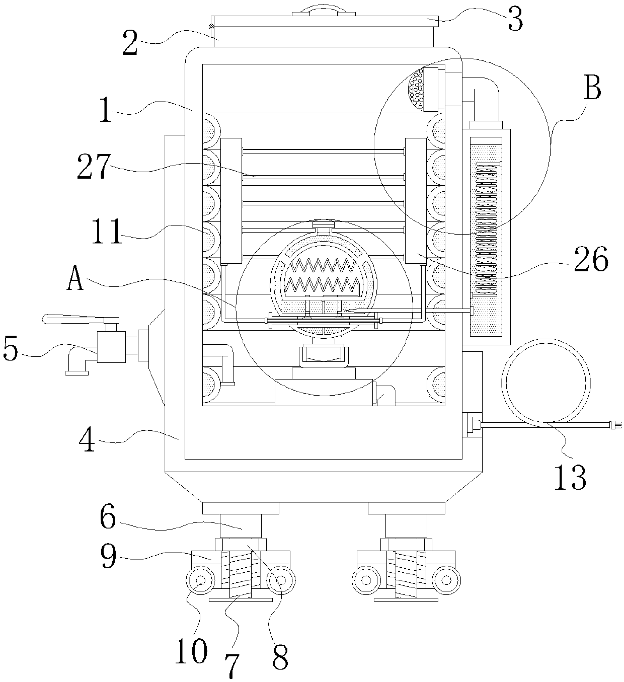
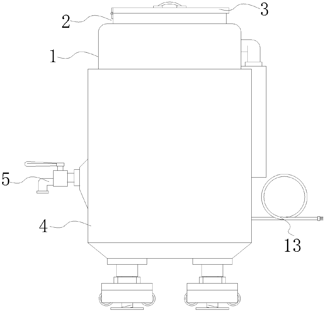
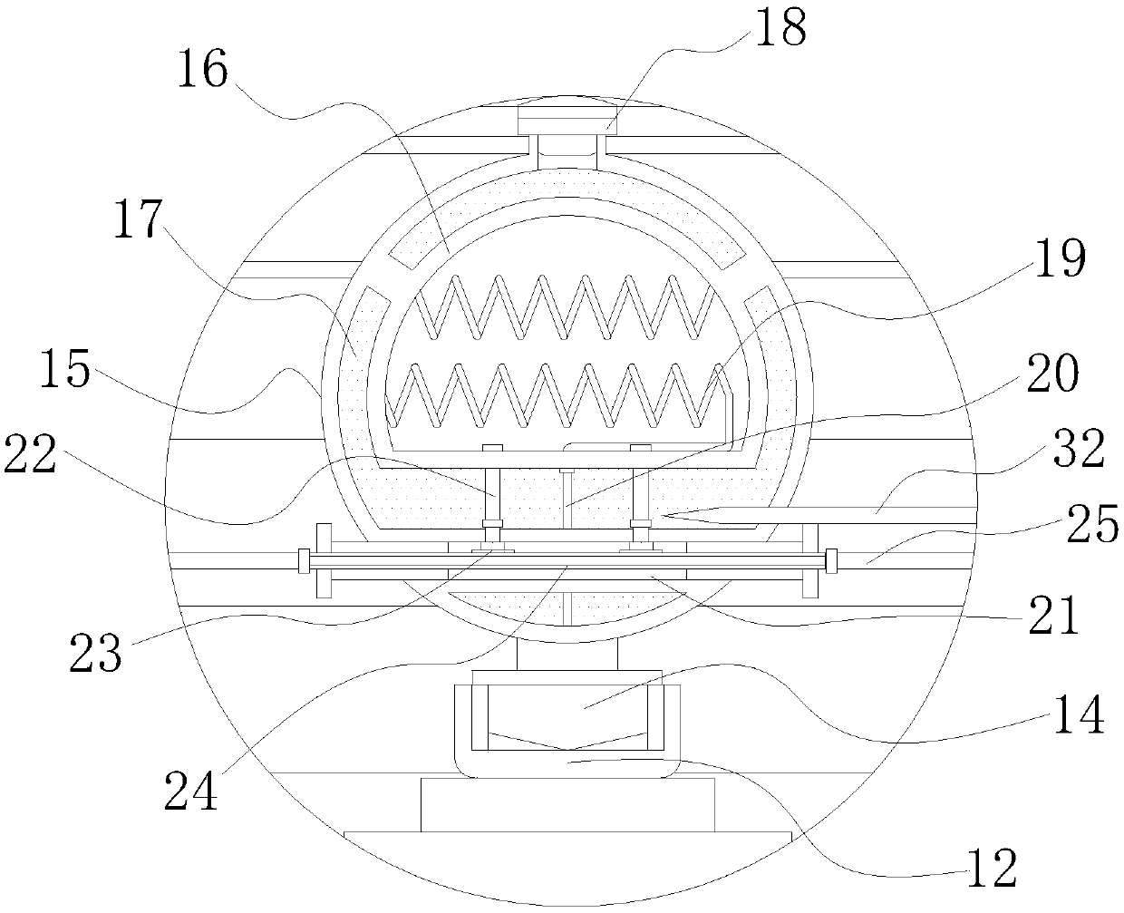
[0026] Such as Figure 1-4As shown, the embodiment of the present invention provides an energy-saving electric boiler, which includes a boiler device 1. The upper part of the boiler device 1 includes a water inlet 2 and a thermal insulation top cover 3. The water inlet 2 is opened on the top of the boiler device 1. The thermal insulation top cover 3 One side of the bottom is hinged to one side of the top of the water inlet 2, so that water can be poured into the interior of the boiler device 1 through the water inlet 2, and the exterior of the boiler device 1 includes an insulation jacket 4, and the inner wall of the insulation jacket 4 is connected to the boiler The outer side of the device 1 is socketed, so that the heat preservation tube 4 can ensure that the heat inside the boiler device 1 will not be lost quickly. Inserting, one end of the faucet 5 runs through the left side of the insulation jacket 4 and extends to the inside of the boiler device 1, the inner cavity of t...
PUM
 Abstract
Description
Claims
Application Information