Non-contact voltage recording device, system and method

A non-contact, voltage technology, applied in the direction of measuring device, only measuring voltage, signal transmission system, etc., can solve the problems such as time-consuming and energy-consuming of testers, high wiring risk, short circuit of voltage transformer, etc., to improve efficiency and improve efficiency. Safety, immunity from electromagnetic interference, and the effect of ensuring personal safety

Pending Publication Date: 2019-04-02
STATE GRID JIANGSU ELECTRIC POWER CO ELECTRIC POWER RES INST +2
View PDF7 Cites 2 Cited by
  • Summary
  • Abstract
  • Description
  • Claims
  • Application Information

AI Technical Summary

Problems solved by technology

Once there is a problem with the measurement equipment, it will directly threaten the safety of the power equipment under test, such as causing high-voltage conductor grounding, open circuit of the end screen, short circuit of voltage transformer, etc.
This voltage signal measurement method has a great impact on the safety of power equipment, and the wiring is very dangerous. For example, the capacitor voltage divider needs to be transported by a crane, and the terminal screen wiring of the transformer bushing needs to be climbed. potential risks

Method used


Image

  • Non-contact voltage recording device, system and method
  • Non-contact voltage recording device, system and method
  • Non-contact voltage recording device, system and method

Examples


Embodiment Construction

[0019] The technical solutions of the present invention will be further described below in conjunction with the accompanying drawings and embodiments.

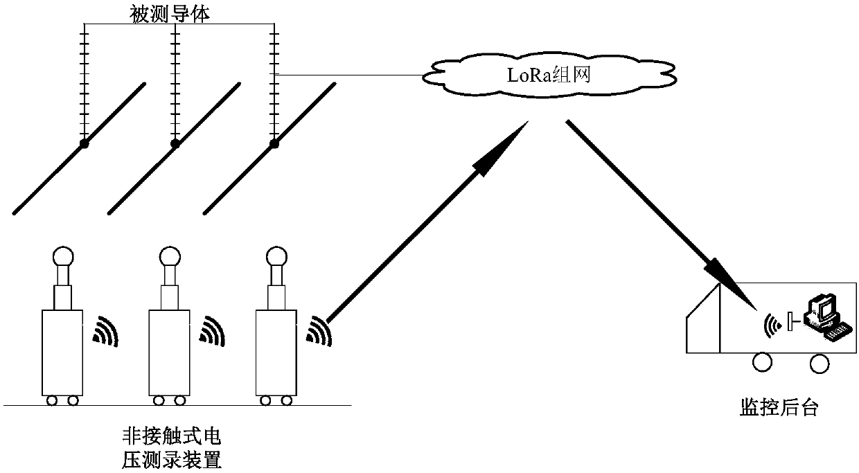
[0020] A kind of non-contact voltage recording system described in the present invention, such as figure 1 As shown, including the measured conductor, non-contact voltage recording device and monitoring background. One non-contact voltage recording device can measure one-phase voltage, and three devices are needed to test three-phase voltage. The device is movable. During the measurement process, the non-contact voltage recording device is placed directly under the measured conductor, and the height and voltage division ratio of the device are adjusted according to the measured voltage level, and the space electric field effect is used to measure the transformer or transmission. The transient voltage signal of the line, and the transient signal is sent to the wireless monitoring background after being saved locally. The moni...


PUM


Abstract

The invention discloses a non-contact voltage recording device, system and method. The system comprises a conductor to be recorded, the non-contact voltage recording device, and a monitoring background. The non-contact voltage recording device arranged under the conductor to be recorded comprises a photoelectric sensing module used for obtaining an electric field intensity of the conductor to be recorded, a laser module, a signal acquiring and processing module for converting the electric field intensity to a voltage of the conductor to be recorded, and a wireless communication module for sending test data to the monitoring background. The photoelectric sensing module is respectively connected with the laser module and the signal acquiring and processing module through optical fibers, andthe signal acquiring and processing module is connected with the wireless communication module. The monitoring background comprises a server used for receiving, storing, and forwarding the data, and acomputer terminal for processing the test data. According to the non-contact voltage recording device, system and method, being in direct contact with the voltage measuring device and the power equipment is avoided, the lapping operation of the test personnel is omitted, so that the test efficiency and the safety are greatly improved, and the safety of the equipment to be recorded and the measuring personnel can be ensured.

Description

technical field [0001] The invention relates to a voltage measuring and recording system used for starting and debugging a substation, in particular to a non-contact voltage measuring and recording device and a measuring and recording system including the device. Background technique [0002] Before the new high-voltage substation and high-voltage transmission line are put into operation, in order to assess the insulation performance of the substation and the line, it is necessary to continuously open and close the transformer and transmission line through the circuit breaker to simulate the electromagnetic transient process of the system. During the test, the voltage signal of the transformer and the transmission line needs to be measured to reflect the multi-voltage situation during the operation and to assess the insulation condition. [0003] The existing voltage signal measurement system needs to be directly connected to the power equipment, including the following type...

Claims


Application Information

Patent Timeline
Patent Type & Authority Applications(China)
IPC IPC(8): G01R19/00G01R31/12G08C17/02
CPCG08C17/02G01R19/0084G01R31/1218
Inventor 徐阳陶风波张照辉胡成博马勇徐江涛贺恒鑫
Owner STATE GRID JIANGSU ELECTRIC POWER CO ELECTRIC POWER RES INST
Why Eureka
Try Eureka