A sensor fault adjustment method for aero-engine
A technology for aero-engine and sensor failures, applied in control/regulation systems, instruments, adaptive control, etc., can solve problems such as slow response speed and large amount of computation
- Summary
- Abstract
- Description
- Claims
- Application Information
AI Technical Summary
Problems solved by technology
Method used
Image
Examples
example
[0150] 1. Establish aero-engine dynamics model
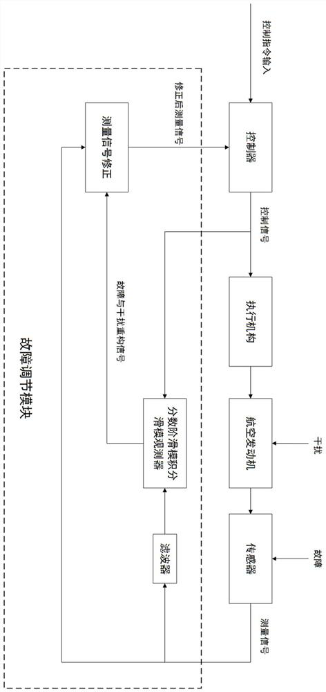
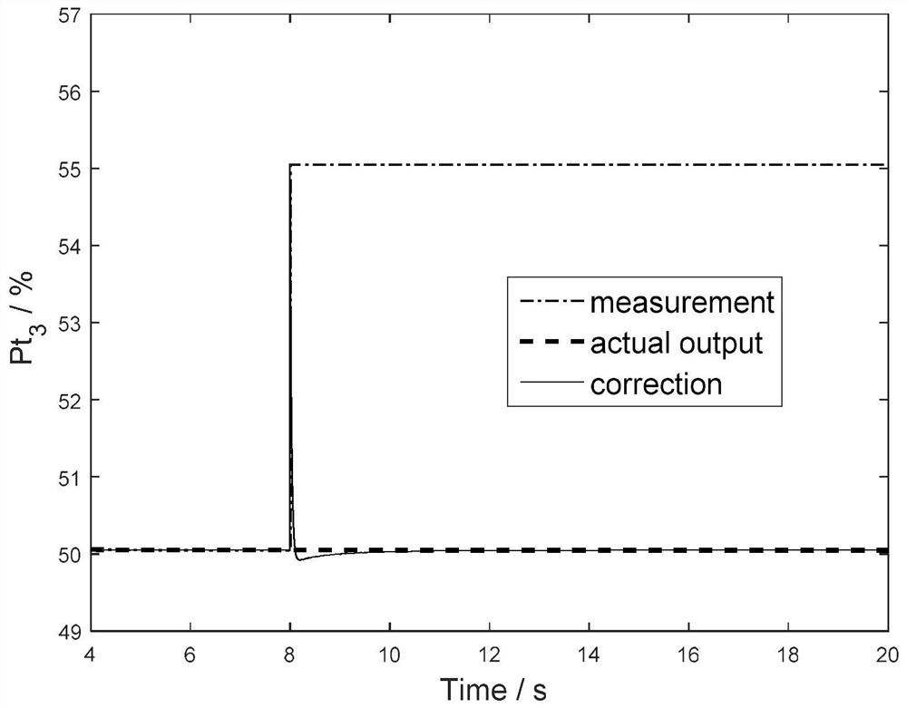
[0151] The aeroengine of the present invention includes all gas turbine engines, and the engine model used in this example is a turbofan engine with a large bypass ratio, dual rotors, and non-adjustable nozzle area, and it is not limited to the turbofan engine. Only the dynamic characteristics of the two rotors are considered, so the state variable of the system is selected as: x=[N 1 N 2 ] T , N 1 , N 2 are the rotational speeds of the low-pressure rotor and the high-pressure rotor, respectively. The input variable is u=W f , W f For fuel supply. According to the common turbofan engine sensor arrangement scheme, the output variable is selected as y=[N 1 N 2 Pt 3 Tt 46 ], Pt 3 is the total pressure at the outlet of the high pressure compressor, Tt 46 is the total outlet temperature of the low-pressure turbine.
[0152] For a turbofan engine with a large bypass ratio, most of its thrust is generated by the fan, ...
PUM
 Abstract
Description
Claims
Application Information
 - R&D
- Intellectual Property
- Life Sciences
- Materials
- Tech Scout
- Unparalleled Data Quality
- Higher Quality Content
- 60% Fewer Hallucinations
Browse by: Latest US Patents, China's latest patents, Technical Efficacy Thesaurus, Application Domain, Technology Topic, Popular Technical Reports.
© 2025 PatSnap. All rights reserved.Legal|Privacy policy|Modern Slavery Act Transparency Statement|Sitemap|About US| Contact US: help@patsnap.com


