
Display device, gate driving circuit, shift register and control method thereof

A shift register and control electrode technology, applied in static memory, static indicator, digital memory information, etc., can solve problems such as high current, and achieve the effect of reducing power consumption, reducing charge and discharge current, and reducing inter-electrode capacitance

Inactive Publication Date: 2019-04-02
BOE TECH GRP CO LTD +1
View PDF7 Cites 4 Cited by
  • Summary
  • Abstract
  • Description
  • Claims
  • Application Information

AI Technical Summary

Problems solved by technology

However, the problem with related technologies is that there is a large overlapping area between the gate and the drain of the transistor, which will form a large capacitance of pF or even nF level. All capacitors will generate repeated charging and discharging, resulting in a large current, which will result in a large power loss

Method used


Image

  • Display device, gate driving circuit, shift register and control method thereof
  • Display device, gate driving circuit, shift register and control method thereof
  • Display device, gate driving circuit, shift register and control method thereof

Examples


Embodiment Construction

[0030] Embodiments of the present invention are described in detail below, examples of which are shown in the drawings, wherein the same or similar reference numerals designate the same or similar elements or elements having the same or similar functions throughout. The embodiments described below by referring to the figures are exemplary and are intended to explain the present invention and should not be construed as limiting the present invention.

[0031] The display device, the gate driving circuit, the shift register and the control method thereof according to the embodiments of the present invention will be described below with reference to the accompanying drawings.

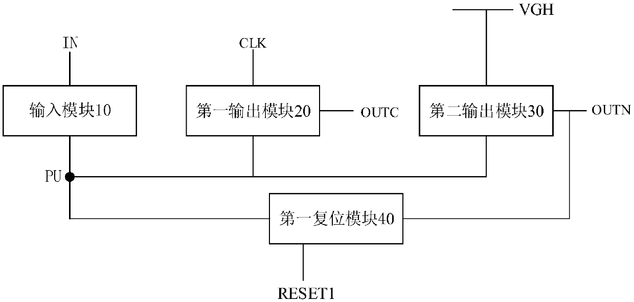
[0032] figure 1 is a schematic block diagram of a shift register according to an embodiment of the present invention. Such as figure 1 As shown, the shift register in the embodiment of the present invention includes: an input module 10 , a first output module 20 , a second output module 30 and a first rese...


PUM


Abstract

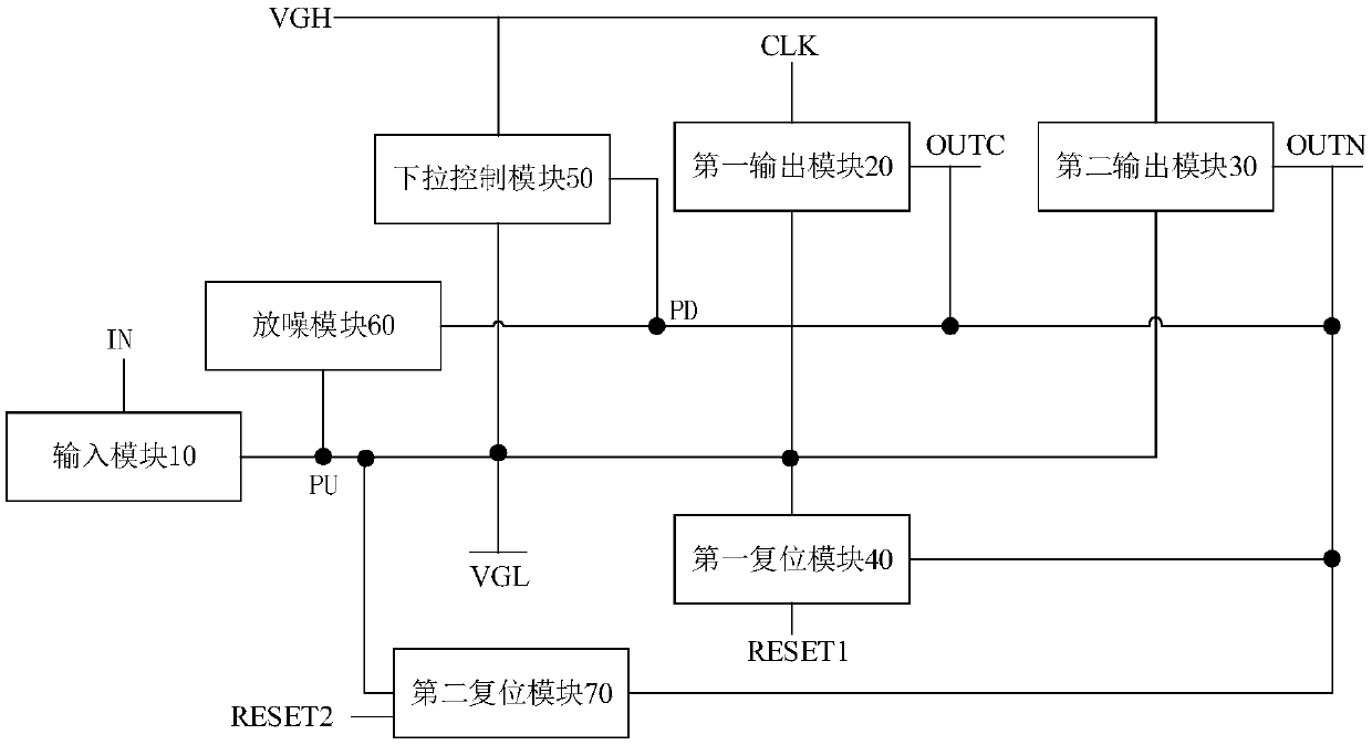
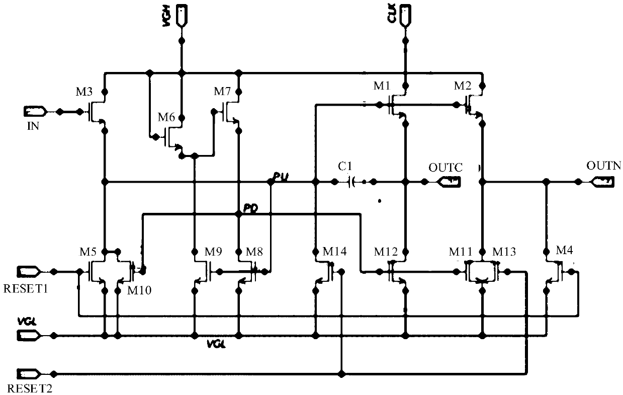
The invention discloses a display device, a gate driving circuit, a shift register and a control method thereof. The shift register comprises an input module, a first output module, a second output module and a first reset module, wherein the input module is used for setting a pull-up node as valid working potential under the control of a signal input terminal; the first output module is used forwriting the voltage of a clock signal terminal into a cascade signal output terminal under the control of the pull-up node; the second output module is used for writing the voltage of a first power terminal into a gate signal output terminal under the control of the pull-up node; and the first reset module is used for setting the gate signal output terminal and the pull-up node as invalid workingpotential under the control of the first reset signal terminal. The shift register disclosed by the embodiment of the invention separates the cascade signal output terminal and the gate signal outputterminal, thereby connecting a clock signal to a smaller transistor, reducing the inter-electrode capacitance, and thus reducing the power consumption of the gate driving circuit.

Description

technical field [0001] The present invention relates to the field of display technology, in particular to a shift register, a gate drive circuit, a display device and a control method for the shift register. Background technique [0002] With the popularity of electronic products such as mobile phones and notebooks, consumers and terminal manufacturers pay more and more attention to the power consumption performance of electronic products. As an important component of an electronic product, the power consumption saving of a display device such as a liquid crystal display (Liquid Crystal Display, LCD) is particularly important. Wherein, the array substrate row driving circuit (Gate Driver on Array, GOA) is used as the driving circuit of the LCD display, and more than 80% of its power consumption is generated by a clock signal with a relatively high frequency. [0003] In the GOA circuit of the related art, the clock signal is usually connected to the transistor with the larg...

Claims


Application Information

Patent Timeline
Patent Type & Authority Applications(China)
IPC IPC(8): G09G3/36G11C19/28
CPCG09G3/3696G09G2310/0286G11C19/28
Inventor 吴君辉毕鑫郭建东蒲巡吴忠山
Owner BOE TECH GRP CO LTD
Learn More