
A Fabry-Perot Antenna with High Gain and Low Radar Cross Section

A radar cross-section, high-gain technology, applied in the field of communication antennas and missile antennas, high-gain, low radar cross-section Fabry-Perot antennas, can solve the problems of poor gain enhancement effect and poor radar cross-section reduction effect, and achieve reduction Metal strip structure, optimize the overall structure, overcome the effect of complex structures around reflective surfaces and radiating antennas

Active Publication Date: 2021-01-05
XIDIAN UNIV
View PDF9 Cites 0 Cited by
  • Summary
  • Abstract
  • Description
  • Claims
  • Application Information

AI Technical Summary

Problems solved by technology

However, when the x-polarized electromagnetic wave is incident, the maximum reduction of the antenna is 14.9dBsm, and the in-band reduction is 4dBsm. When the y-polarized electromagnetic wave is incident, the reduction in the working frequency band is 4dBsm, and the radar cross section of the antenna is reduced. less effective
And the antenna gain improvement effect is only 3dBi, the gain improvement effect is poor

Method used


Image

  • A Fabry-Perot Antenna with High Gain and Low Radar Cross Section
  • A Fabry-Perot Antenna with High Gain and Low Radar Cross Section
  • A Fabry-Perot Antenna with High Gain and Low Radar Cross Section

Examples


Embodiment 1

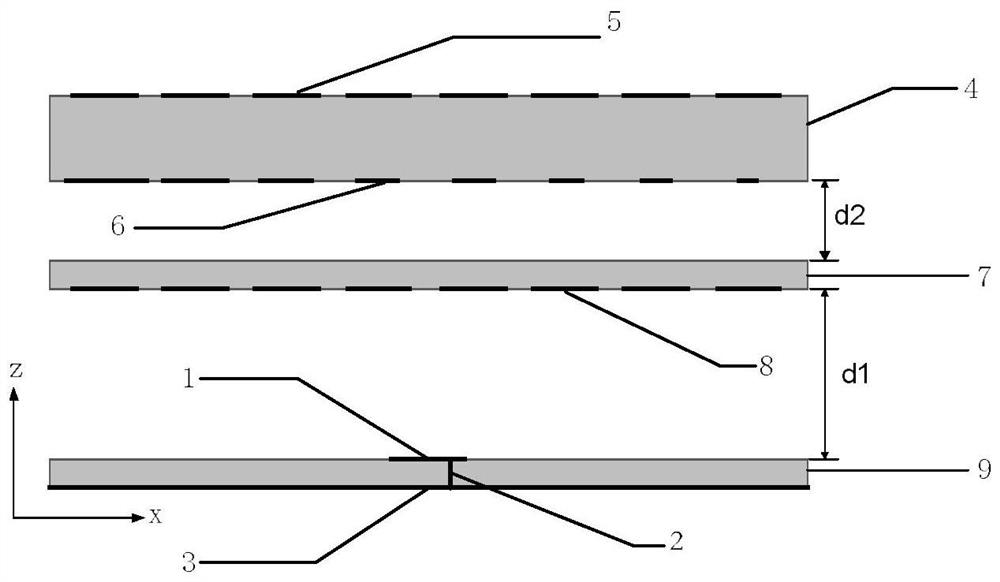
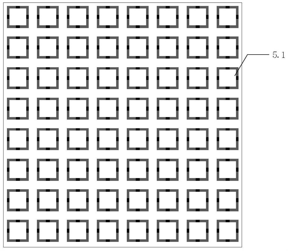
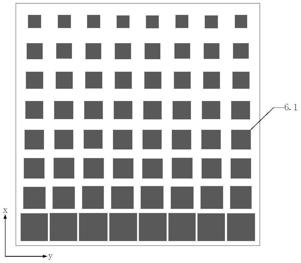
[0031] refer to figure 1 , figure 2 , image 3 and Figure 4 ,

[0032] A Fabry-Perot antenna with high gain and low radar cross section, comprising an antenna radiator 1, a feed structure 2, a metal floor 3, and a first wave-absorbing coating printed on the upper and lower surfaces of a first dielectric substrate 4 5. The second reflective coating 6 and the third reflective coating 8 printed on the lower surface of the second dielectric substrate 7; the antenna radiator 1 is printed on the upper surface of the third dielectric substrate 9, and the feeding structure 2 Penetrating through the third dielectric substrate 9 and connected to the antenna radiator 1 and the metal floor 3, the first wave-absorbing cladding 5 is distributed in a checkerboard pattern, and consists of N×N square absorbers with the same structure periodically arranged Composed of unit 5.1, wherein, N≥2, N is a positive integer, each square absorbing unit 5.1 is a metal ring structure, and the four si...

Embodiment 2

[0045] This embodiment has the same structure as Embodiment 1, only the following parameters are adjusted:

[0046] refer to figure 1

[0047] The thickness of the air layer between the second dielectric substrate and the third dielectric substrate is d1, d1=10mm, the thickness of the air layer between the first dielectric substrate and the second dielectric substrate is d2, d2=0.2mm

[0048] refer to Figure 5

[0049] Square metal ring patch unit 8.1, when the outer length is Wout=9mm, the width of the metal ring is Ws, Ws=2mm. The side length of the square metal patch unit is Wm=2mm, the side length of the square metal ring on the square absorbing unit 5.1 is a=3mm, and the width of the metal ring is W1=0.1mm.

Embodiment 3

[0051] This embodiment has the same structure as Embodiment 1, only the following parameters are adjusted:

[0052] refer to figure 1

[0053] The thickness of the air layer between the second dielectric substrate and the third dielectric substrate is d1, d1=26mm, the thickness of the air layer between the first dielectric substrate and the second dielectric substrate is d2, d2=1.8mm

[0054] refer to Figure 5

[0055] Square metal ring patch unit 8.1, when the outer side length is Wout=17mm, the width of the metal ring is Ws, Ws=6mm. The side length Wm=17mm of the square metal patch unit, the side length a=9mm of the square metal ring on the square absorbing unit 5.1, the width of the metal ring is W1, W1=1.1mm.

[0056] Below in conjunction with accompanying drawing and the present invention will be further described

[0057] Simulation content and conditions

[0058] refer to Figure 7 , the present invention simulates the antenna in Embodiment 1 through the electro...


PUM

PropertyMeasurementUnit
widthaaaaaaaaaa
thicknessaaaaaaaaaa
thicknessaaaaaaaaaa

Abstract

The invention provides a Fabry-Perot antenna with a high gain and a low radar cross section. By adoption of a three-layer antenna coating design, the Fabry-Perot antenna has a radar cross section lower than that of a traditional microstrip antenna under the premise of having better radiation characteristics than the traditional microstrip antenna; and the Fabry-Perot antenna provided by the invention comprises an antenna radiation body, a feed structure, a metal floor, a first wave absorbing coating and a second reflection coating, which are printed on upper and lower surfaces of a first dielectric substrate, and a third reflection coating printed on the lower surface of a second dielectric substrate; the first wave absorbing coating is composed of N*N square wave absorbing units that have the same structure and are periodically arranged, and the second reflection coating and the third reflection coating are respectively composed of N*N square metal ring patches and square metal patchunits, which have the same structure and are periodically arranged. The Fabry-Perot antenna provided by the invention solves the technical problem of poor in-band radar cross section reduction effectin the prior art, greatly improves the gain of the antenna, and is suitable for the field of guided missile radar and satellite communication requiring low observable characteristics.

Description

technical field [0001] The invention belongs to the technical field of antennas, and in particular relates to a Fabry-Perot antenna with high gain and low radar section, which can be applied to communication antennas and missile antennas with low observable characteristics. Background technique [0002] In the traditional communication field, the signal transmitting and receiving system is one of the most important components of the entire communication platform, the antenna is the core part of the system, and the radiation characteristics are the main indicators to measure the quality of the antenna. As antennas are increasingly used in military fields such as aircraft, missiles, and ships, people's requirements for antenna scattering characteristics are also getting higher and higher. The key to improving the scattering characteristics is how to reduce the radar cross section, and the radar cross section is the most basic parameter in the scattering characteristics, which ...

Claims


Application Information

Patent Timeline
Patent Type & Authority Patents(China)
IPC IPC(8): H01Q1/38H01Q1/48H01Q1/50H01Q15/14H01Q17/00H01Q19/185
CPCH01Q1/38H01Q1/48H01Q1/50H01Q15/145H01Q17/008H01Q19/185
Inventor 贾永涛张家豪刘英
Owner XIDIAN UNIV
Learn More