Module for controlling the internal energy of a converter

A technology for controlling modules and internal energy, which is applied to the output power conversion device, the structural components of the conversion equipment, and the conversion of AC power input to DC power output.

Inactive Publication Date: 2019-04-02
SUPERGRID INSTITUTE SAS +1
View PDF7 Cites 0 Cited by
  • Summary
  • Abstract
  • Description
  • Claims
  • Application Information

AI Technical Summary

Problems solved by technology

Therefore, these solutions cannot take full advantage of the MMC's ability to control the internal energy of the converter

Method used


Image

  • Module for controlling the internal energy of a converter
  • Module for controlling the internal energy of a converter
  • Module for controlling the internal energy of a converter

Examples


Embodiment Construction

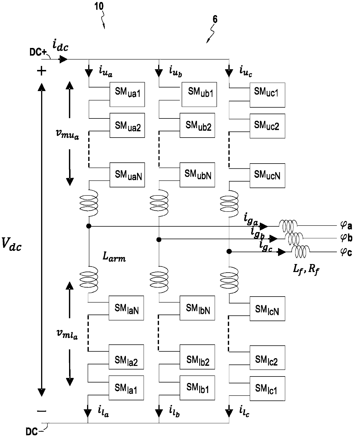
[0125] Figure 6 The embodiment of the invention shown in relates to a modular multilevel converter 10 comprising a control module 12 . Figure 5 An equivalent circuit is shown for the behavior of the inventive converter 10 in a single-phase model. Figure 5 The control module is not shown. Using a single-phase model also simplifies the symbols and diagrams used. In this figure, and in a non-limiting manner, an MMC 10 for converting DC energy into AC energy can be seen.

[0126] In this example, it can be seen that the converter 10 has a DC part 10A, which is connected to a DC supply network 110 in the left part of the figure. In the right part of the figure, it can be seen that the converter 10 has an AC part 10C connected to an AC supply network 120 . exist Figure 5 Medium, L arm and R arm represent the inductance and resistance in the arms, respectively, while L f and R f Represent the inductance and resistance in the phase wire, respectively. i diff represents the...


PUM


Abstract

The invention relates to a multilevel modular converter (10) including a control module (12) for regulating the internal energy stored in the capacitors of the submodules of a half arm of the converter, the control module being capable of keeping the internal energy below an upper limit and/or above a lower limit, by using parameters measured on the DC electrical power supply network (110) and onthe AC electrical power supply network (120) as well as operating power setpoints of the converter.

Description

technical field [0001] The present invention relates to the technical field of modular multilevel converters (MMCs) for converting alternating current (AC) to direct current (DC) and vice versa. [0002] The invention relates more precisely to a high voltage direct current (HVDC) transmission network using DC for transmitting electric power and in which the stations comprise modular multilevel converters. Background technique [0003] In FIG. 1 , a diagram showing a collection 6 of submodules of a multilevel modular converter 10 of the prior art can be seen. For three-phase input / output (with three phase and ), the converter 10 has three conversion legs (legs), which are referenced by the indices a, b and c given to the various components of FIG. 1 . Each conversion branch consists of an upper arm and a lower arm (the upper and lower arms are denoted by the index "u" Indicates the lower arm), each branch connects one terminal DC+ or DC- of the DC supply network to a t...

Claims


Application Information

Patent Timeline
Patent Type & Authority Applications(China)
IPC IPC(8): H02M7/483
CPCH02M7/483H02M7/4835H02M7/493H02M1/0067H02M1/0009H02M7/003
Inventor 篠田康生阿波德尔克里姆·本希伊布泽维尔·吉约戴晶
Owner SUPERGRID INSTITUTE SAS
Why Eureka
Try Eureka