Energy-efficient dispersion-mixing method for large-phase-ratio system and application of method

A high-energy-efficiency, dispersed technology, applied in the field of reactors, can solve the problems that the dispersed phase cannot be highly dispersed and the energy can be used efficiently.

Active Publication Date: 2019-04-05
BEIJING UNIV OF CHEM TECH
View PDF4 Cites 11 Cited by
  • Summary
  • Abstract
  • Description
  • Claims
  • Application Information

AI Technical Summary

Problems solved by technology

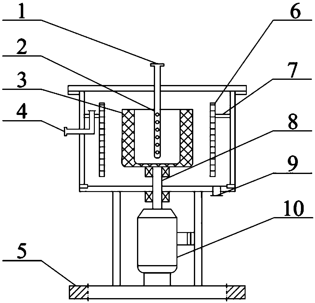
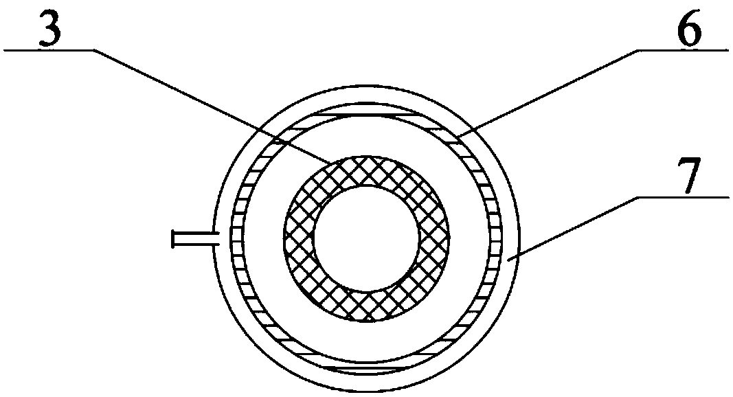
[0005] In order to solve the problem that the current dispersion and mixing method cannot achieve high dispersion of the dispersed phase and efficient utilization of energy, the present invention provides a high-energy-efficiency dispersion-mixing method for large-phase systems, a high-gravity reactor and its application. The high gravity dispersing unit and the falling film mixing unit are set up. The high gravity dispersing unit first disperses the dispersed phase fluid into micro-nano scale droplets, and the falling film mixing unit makes the continuous phase fluid form a flowing liquid film, and then through the high gravity dispersing unit. The droplets collide with the liquid film. Compared with the traditional mixing method, which uses small droplets to mix and stir at the same time, the dispersed phase fluid of this application is fully dispersed before mixing, and then mixed with the continuous phase to increase the disturbance of the two-phase mixing interface. , so that the mixing efficiency is improved, the degree of dispersion is high, and the falling film unit further breaks up the droplets that disperse and hit the liquid film, which improves the utilization rate of energy

Method used


Image

  • Energy-efficient dispersion-mixing method for large-phase-ratio system and application of method
  • Energy-efficient dispersion-mixing method for large-phase-ratio system and application of method
  • Energy-efficient dispersion-mixing method for large-phase-ratio system and application of method

Examples


Embodiment Construction

[0057] In order to illustrate the present invention more clearly, the present invention will be further described below in conjunction with preferred embodiments and accompanying drawings. Similar parts in the figures are denoted by the same reference numerals. Those skilled in the art should understand that the content specifically described below is illustrative rather than restrictive, and should not limit the protection scope of the present invention.

[0058] Various cross-sectional views according to disclosed embodiments of the invention are shown in the drawings. The figures are not drawn to scale, with certain details exaggerated and possibly omitted for clarity of presentation. The shapes of various regions and layers shown in the figure, as well as their relative sizes and positional relationships are only exemplary, and may deviate due to manufacturing tolerances or technical limitations in practice, and those skilled in the art may Regions / layers with different ...


PUM


Abstract

The invention provides an energy-efficient dispersion-mixing method for a large-phase-ratio system and an application of the method. The method includes forming continuous phase fluid into film-shapedflowing through a falling film mixing unit; forming dispersed phase fluid into micro-nano scale droplets through a super-gravity dispersing unit; and mixing the droplets with the continuous phase fluid flowing in a film shape. By arrangement of the super-gravity dispersing unit, the dispersed phase fluid is firstly dispersed into the micro-nano scale liquid droplets, the falling film mixing unitenables the continuous phase fluid to form a flowing liquid film, and then the droplets and the liquid film are impacted through the super-gravity dispersing unit; compared with the traditional mixingmethod, the dispersed phase fluid is uniformly mixed in a small liquid droplet mode and stirred at the same time; the dispersed phase fluid is fully dispersed before mixing, and then is mixed with the continuous phase, so that the disturbance of the two-phase mixing interface is increased, the mixing efficiency is improved, and the dispersion degree is high; and in addition, the falling film unitfurther crushes the liquid droplets dispersed and impacted on the liquid film, so that the energy utilization rate is improved.

Description

technical field [0001] The invention relates to the technical field of reactors, and more specifically, to a high-energy-efficiency dispersion-mixing method for large phase systems and its application. Background technique [0002] The dispersion mixing process refers to the process of distributing a certain component (dispersed phase) to another component (continuous phase) after being fully refined. The dispersion and mixing effect can be measured according to the size of the dispersed phase droplet size. For a certain volume of dispersed phase, the smaller the droplet size, the larger the interphase mass transfer surface area, and the better the dispersion and mixing effect. [0003] Dispersion mixing technology is widely used in petroleum, chemical, food, pharmaceutical, dyestuff, metallurgy, sewage treatment and other process industries, and plays an important role in homogenization, emulsification, polymerization and other occasions. However, in these process industri...

Claims


Application Information

Patent Timeline
Patent Type & Authority Applications(China)
IPC IPC(8): B01F3/08B01F3/20B01J19/18B01J14/00B01F23/70
CPCB01J14/00B01J19/0053B01J19/18B01F23/4105B01F23/70
Inventor 初广文贾向碧罗勇蔡勇孙宝昌邹海魁陈建峰
Owner BEIJING UNIV OF CHEM TECH
Why Eureka
Try Eureka