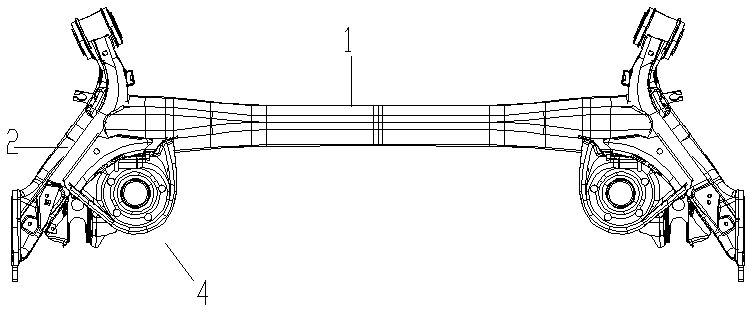
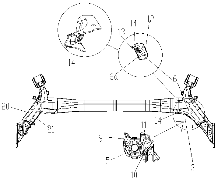
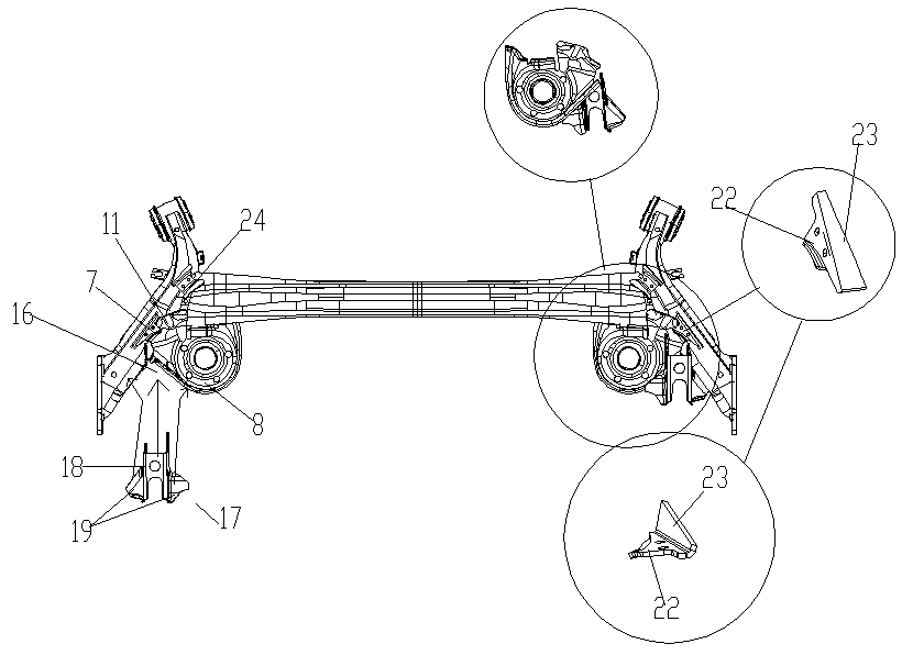
Hydraulic variable-cross-section closed torsion beam
A variable cross-section, closed technology, applied in elastic suspension, interconnection system, suspension, etc., can solve the problems of increased cost and many manufacturing processes, and achieve the effect of simplifying the manufacturing process, low cost, and strengthening the overall sealing performance
- Summary
- Abstract
- Description
- Claims
- Application Information
AI Technical Summary
Problems solved by technology
Method used
Image

Examples
Embodiment Construction
[0024] Below by embodiment, in conjunction with accompanying drawing, the technical scheme of the present invention is as preferred specific description:
[0025] It should be noted that the words "front", "rear", "left", "right", "upper" and "lower" used in the following description refer to the directions in the drawings, and the words "inner" and "outer "respectively refer to towards or away from. If it is to describe the structure of the shell cavity, it is to describe the inside and outside of the shell, the direction of the geometric center of the invention or its specific components. The connection method specified in this embodiment is generally Welded connections, bolt or screw connections, snap-fit connections, snap-fit connections, etc. of the prior art are all prior technologies well known to those skilled in the art.
[0026] The present invention is achieved through the following technical proposals: a closed torsion beam with variable cross-section hydraulic...
PUM
 Abstract
Description
Claims
Application Information
 - R&D
- Intellectual Property
- Life Sciences
- Materials
- Tech Scout
- Unparalleled Data Quality
- Higher Quality Content
- 60% Fewer Hallucinations
Browse by: Latest US Patents, China's latest patents, Technical Efficacy Thesaurus, Application Domain, Technology Topic, Popular Technical Reports.
© 2025 PatSnap. All rights reserved.Legal|Privacy policy|Modern Slavery Act Transparency Statement|Sitemap|About US| Contact US: help@patsnap.com