Support joint structure for rebar truss plates and framework formwork

A steel truss and formwork support technology, which is applied in the field of steel truss slab and frame formwork support node structures, can solve the problems of complex installation nodes, weak load-bearing capacity, and low connection strength, and achieve convenient and easy-to-operate connection of connecting bars and smooth node positions , the effect of simple connection of connecting ribs

Pending Publication Date: 2019-04-05
ZHE JIANG ZHONGYI BUILDING MATERIALS TECH CO LTD
View PDF11 Cites 3 Cited by
  • Summary
  • Abstract
  • Description
  • Claims
  • Application Information

AI Technical Summary

Problems solved by technology

Therefore, there are the following problems in the construction of the self-supporting steel grid frame composite formwork: the installation nodes of the steel grid frame composite formwork are complicated, the connection strength is low, and the load-bearing capacity is weak; low efficiency

Method used


Image

  • Support joint structure for rebar truss plates and framework formwork
  • Support joint structure for rebar truss plates and framework formwork
  • Support joint structure for rebar truss plates and framework formwork

Examples


Embodiment 1

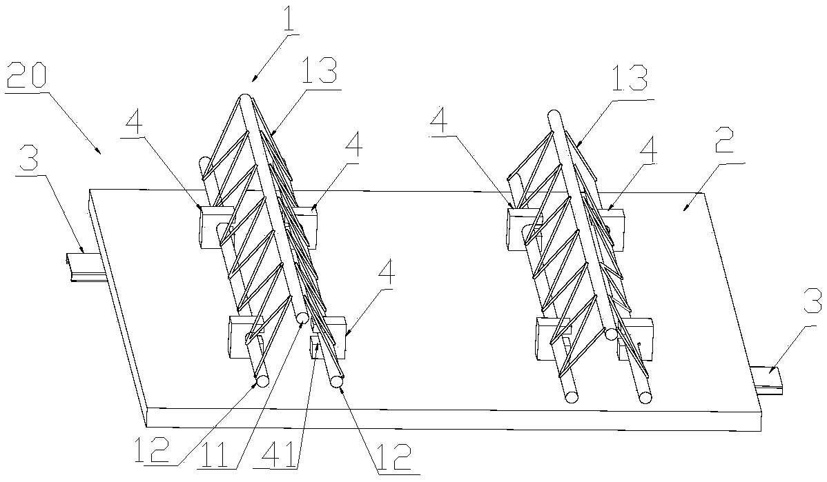
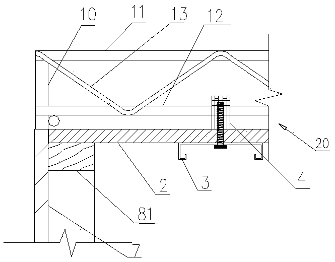
[0042] Such as figure 1A detachable steel truss panel is shown, which includes a steel truss 1 , a connector 4 , a floor deck 2 and a support 3 . The steel bar truss 1 includes an upper chord steel bar 11 and two lower chord steel bars 12 , and the two lower chord steel bars 12 are respectively welded and connected to the upper chord steel bars 11 through web steel bars 13 . The two lower chord steel bars 12 are connected with the connecting piece 4 relative to each other. The connecting piece 4 includes a slot 41 through the connecting piece 4 with a side opening, and a threaded hole is provided at the lower end of the connecting piece 4 . The connectors 4 are clamped on the two lower chord steel bars 12 in pairs, and each pair of connectors 4 is arranged longitudinally on the steel bar truss 1 . figure 1 The length of the shown detachable steel truss slab 20 can be designed according to requirements, generally 1-3m, and its width is two steel trusses 2, and in some embodim...

Embodiment 2

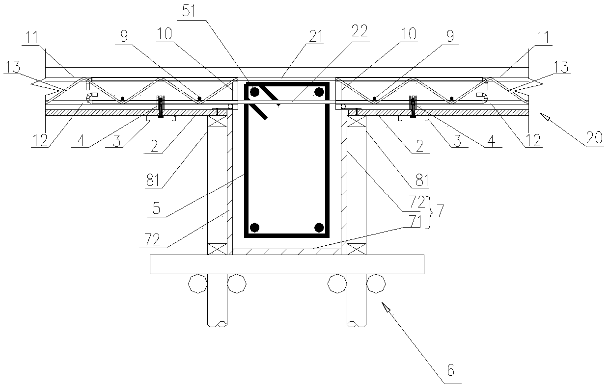
[0058] The difference between this embodiment and Embodiment 1 is that the frame template 7 is a frame-plate combination mold, and the frame-plate combination mold includes two side templates 72 and a bottom template 71 assembled into a groove shape for placing the frame structure 5. The side template 72 includes side panels 723 and side frames connected to the sides of the side panels 723, the bottom template 71 includes a bottom panel 712 and a bottom frame 711 connected to the bottom panel 712, and the bottom frame 711 is connected to both side frames.

[0059] Existing beam formwork is usually steel formwork or wood formwork, each has advantages and disadvantages. In the embodiment, the light and easy-to-cut materials such as wood, bamboo, and plastic are used as the side plate 723 and the bottom plate 712, and side frames are arranged around the side plate 723, and the bottom plate 712 is provided with a bottom frame 711. Box 711 is connected to the boxes on both sides re...


PUM


Abstract

The invention relates to the field of construction of concrete structure buildings, in particular to a support joint structure for rebar truss plates and a framework formwork. The structure comprisesa framework structure and the rebar truss plates located at the two sides of the framework structure, the framework formwork is arranged at the outer side of the framework structure and comprises twoside formwork bodies and a bottom formwork body, a floor support plate is arranged at one side of each side formwork body, and the heights of the upper ends of the side formwork bodies are equal to that of the upper surfaces of the floor support plates; the structure comprises a first supporting part for supporting the end of each rebar truss plate, and a supporting base is arranged at the end ofeach rebar truss and located above the corresponding first supporting part. Through connecting bars, the rebar truss plates at the two sides of the framework structure are connected, and the connecting bars are simple and convenient in connection and easy to operate; meanwhile, floor plates after setting of cast concrete have high connecting strength and bearing capability, through support of thefirst supporting parts, staggering of side portions of the rebar truss plates and side formwork bodies is small, and after forming, the joint parts of the floor plates are level.

Description

technical field [0001] The invention relates to the field of concrete structure building construction, in particular to a steel bar truss plate and frame formwork support node structure. Background technique [0002] At present, horizontal structural formwork projects in my country's construction industry generally adopt bent frame support, supplemented by wooden squares and plywood or formwork. Its technological principle provides support for the bottom formwork by setting up a bent support system to meet the requirements of bearing capacity and deformation during the construction stage. [0003] Chinese patent application number: 2013102995081, patent name: self-supporting steel grid frame composite formwork and its construction method, discloses a steel grid frame composed of multiple rows of longitudinal steel trusses and multiple rows of horizontally distributed steel bars, and the steel grid frame and detachable The combination of formwork realizes the less-supported ...

Claims


Application Information

Patent Timeline
Patent Type & Authority Applications(China)
IPC IPC(8): E04B1/38E04B5/16E04G11/48
CPCE04B1/38E04B5/16E04G11/48
Inventor 陈永德叶健
Owner ZHE JIANG ZHONGYI BUILDING MATERIALS TECH CO LTD
Why Eureka
Try Eureka