Spiral lattice plate shell-and-tube heat exchanger

A heat exchanger and spiral technology, which is applied in the field of spiral pattern plate shell-and-tube heat exchangers, can solve the problem of reducing the heat exchange efficiency of the shell-and-tube heat exchanger, shortening the service life of the shell-and-tube heat exchanger, and reducing the heat exchange rate. problems such as pump efficiency, to achieve the effect of preventing accumulation, reducing pressure loss and saving pump work

Inactive Publication Date: 2019-04-05
XI AN JIAOTONG UNIV
View PDF10 Cites 4 Cited by
  • Summary
  • Abstract
  • Description
  • Claims
  • Application Information

AI Technical Summary

Problems solved by technology

[0003] There are many disadvantages in the traditional bow-shaped baffle shell-and-tube heat exchanger: (1) The fluid on the shell side constantly changes the flow velocity and flow direction, the pressure drop loss is very significant, and the pump power consumption is huge; (2) There are The flow stagnation area reduces the efficiency of the heat exchanger and easily causes dirt accumulation; (3) The fluid on the shell side continuously scours the heat exchange tube bundle laterally, which induces the vibration of the tube bundle, causes fatigue damage of the tube bundle, and shortens the service life; (4) folds There are leakage flow and bypass branch flow between the flow plate and the shell, which reduces the heat transfer efficiency of the shell and tube heat exchanger
Although the grid plate heat exchanger reduces the pressure drop loss, the heat transfer efficiency is also significantly reduced; and the high-velocity fluid longitudinal flow impacts the plate, which will shorten the service life of the shell-and-tube heat exchanger

Method used


Image

  • Spiral lattice plate shell-and-tube heat exchanger
  • Spiral lattice plate shell-and-tube heat exchanger
  • Spiral lattice plate shell-and-tube heat exchanger

Examples


Embodiment Construction

[0030] The present invention will be described in detail below in conjunction with the accompanying drawings and specific embodiments.

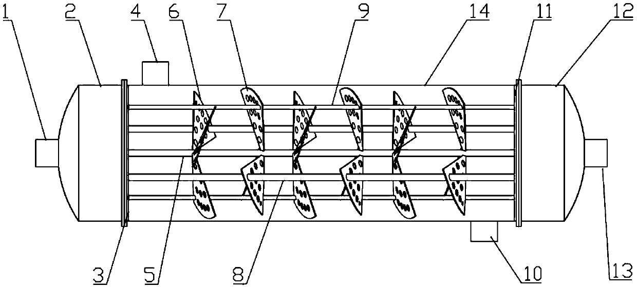
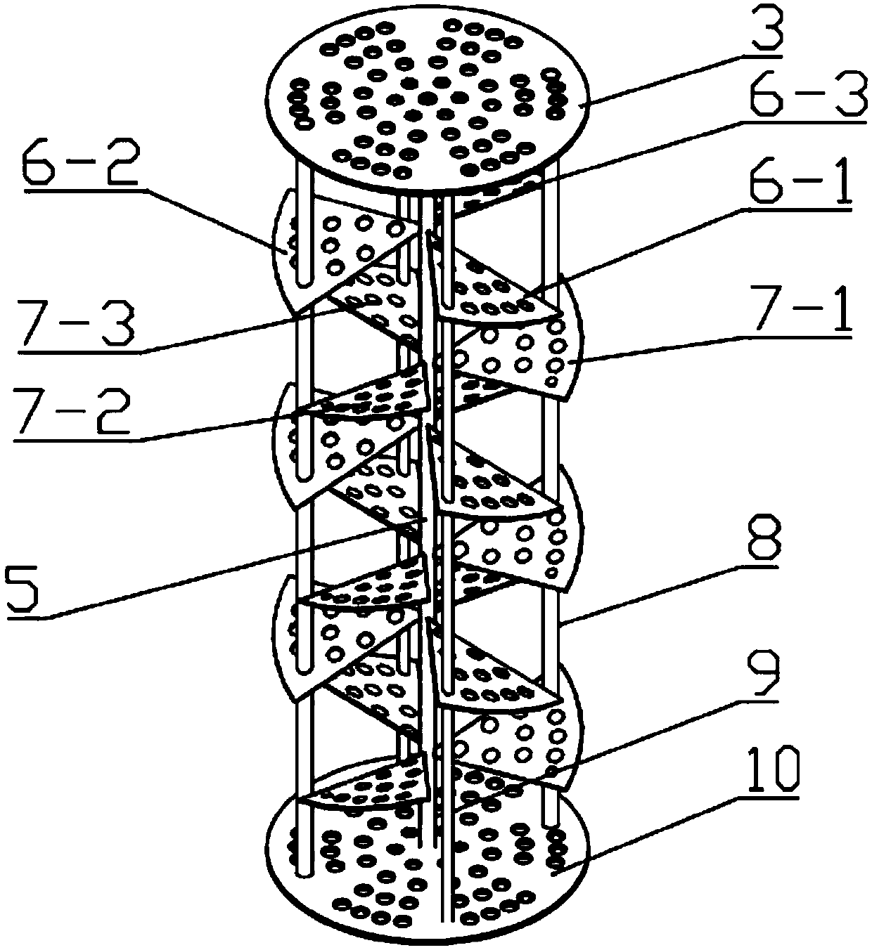
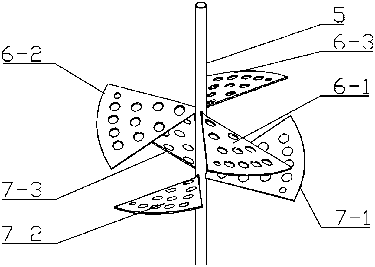
[0031] A shell-and-tube heat exchanger with spiral grille baffles, including a shell, a central tube located in the shell, and two tube sheets respectively connected to two ends of the shell. The tube sheets are respectively connected to heads, one of which is The tube side inlet is set on the top, and the tube side outlet and liquid discharge hole are set on the other head. The heat exchange tube bundle passes through the holes on the spiral grille baffle and is fixed in parallel between the two tube sheets, and is arranged on the shell. There are shell-side inlets and shell-side outlets. The spiral grille baffles have a spiral rotation angle, and the spiral grille baffles are located between the central tube and the shell. tube connection. The fluid on the shell side flows from the gap in the middle of the blades of the spiral gratings to ...


PUM


Abstract

The invention relates to a spiral lattice plate shell-and-tube heat exchanger comprising a shell, a central pipe, six pull rods, two tube plates located at the two ends of the shell separately, a heatexchange tube bundle, a plurality of spacer tubes and a plurality of groups of spiral lattice baffles located between the central tube and the shell; the tube plates are connected with seal heads, and one seal head is provided with a drain hole and a tube side inlet; the other seal head communicates with a tube side outlet; and the spiral lattice baffles are composed of two groups of spiral lattice plates of which the rotation directions are different. The shell side fluid flows out from gaps of first group of the baffles, and flows longitudinally; the fluid is disturbed in a small spiral flow form when meeting the second group of the baffles; and in this process, pressure drop of the shell side is reduced through the longitudinal flow form, and the disturbance of the shell side fluid isenhanced through the spiral flow form. Through the spiral lattice baffle structure mode adopted by the heat exchanger, the shell-and-tube heat exchanger can be more compact, and the heat exchange efficiency is improved; the flow resistance is reduced, and the vibration of the heat exchange tube bundle and fouling deposits of the shell side are reduced; and the service life of the shell-and-tube heat exchanger is prolonged.

Description

technical field [0001] The invention relates to a shell-and-tube heat exchanger used in the fields of petroleum smelting, chemical industry, energy, electric power, etc., in particular to a shell-and-tube heat exchanger with spiral grating plates. Background technique [0002] The shell and tube heat exchanger is the most widely used heat exchanger at present, and it is widely used in the fields of petroleum smelting, chemical industry, energy and electric power. According to statistics, in the world heat exchanger market, shell and tube heat exchangers account for 37% of the total; among them, the proportion is as high as 70% in the petrochemical industry. The shell-and-tube heat exchanger is a kind of partition wall heat exchanger. The cold and hot fluids are located on both sides of the heat exchange tube bundle wall, and the heat is transferred from the hot fluid to the cold fluid through the tube bundle wall. In addition, baffles are arranged on the shell side, and the...

Claims


Application Information

Patent Timeline
Patent Type & Authority Applications(China)
IPC IPC(8): F28D7/16F28F9/24
CPCF28D7/16F28F9/24F28D7/1669F28F9/22F28F2009/228
Inventor 曾敏陈坚赵鹏波张攀王秋旺
Owner XI AN JIAOTONG UNIV
Why Eureka
Try Eureka