Angle-adjustable CT (Computed Tomography) device

A technology of angle and vacuum chuck, which is applied in the direction of measuring devices, instruments, scientific instruments, etc., can solve the problem of poor reconstructed image quality, lack of three-dimensional angle adjustment mechanism devices for flat panel detectors and X-ray sources, and inability to accurately adjust the focus of X-ray sources To achieve the effect of improving angle controllability and compatibility, increasing angle adjustment range, and reducing application costs

Active Publication Date: 2019-04-05
杭州翔毅科技有限公司
View PDF12 Cites 5 Cited by
  • Summary
  • Abstract
  • Description
  • Claims
  • Application Information

AI Technical Summary

Problems solved by technology

However, the above-mentioned CT structure can only roughly adjust the positions of the X-ray source and the flat panel detector relative to the platform synchronously, and lacks an independent mechanism capable of adjusting the three-dimensional angles of the flat panel detector and the X-ray source, thus making it impossible to precisely adjust the X-ray source The line connecting the focal point and the center point of the flat-panel detector is perpendicular to the imaging surface of the flat-panel detector, resulting in poor reconstruction image quality

Method used


Image

  • Angle-adjustable CT (Computed Tomography) device
  • Angle-adjustable CT (Computed Tomography) device
  • Angle-adjustable CT (Computed Tomography) device

Examples


Embodiment Construction

[0047] In order to make the object, technical solution and advantages of the present invention clearer, the present invention will be further described in detail below in conjunction with the accompanying drawings and embodiments. It should be understood that the specific embodiments described here are only used to explain the present invention, not to limit the present invention.

[0048] In addition, the technical features involved in the various embodiments of the present invention described below can be combined with each other as long as they do not constitute a conflict with each other.

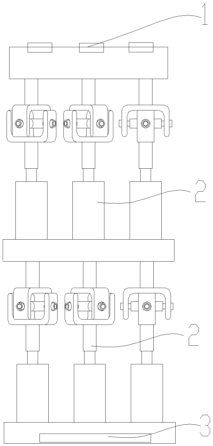
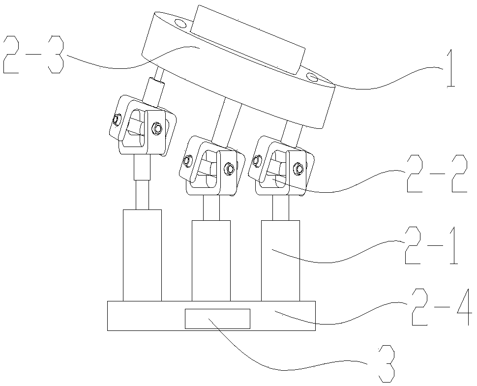
[0049] An angle-adjustable CT device in a preferred embodiment of the present invention, such as figure 1 As shown, including suction cup matrix 1 and drive part 2,

[0050] The sucker matrix 1 is placed on the driving part 2 to fix the object to be measured. The sucker matrix 1 is composed of several electromagnetic chucks and vacuum chucks. Each electromagnetic chuck is equipped with...


PUM

PropertyMeasurementUnit
diameteraaaaaaaaaa
diameteraaaaaaaaaa

Abstract

The invention discloses an angle-adjustable CT (Computed Tomography) device and belongs to the technical field of computer tomography equipment. The device comprises a suction cup matrix and a drive part, wherein the suction cup matrix adsorbs and fixes a to-be-detected object; the drive part is composed of a plurality of drive units connected in series; each of the drive units is composed of an electromagnetic actuator, a rotating part, an upper platform and a lower platform; the electromagnetic actuator and the rotating part are in one-to-one association and are evenly placed between the upper platform and the lower platform; the rotating part is formed by connecting a rotating body, a cross shaft, a connecting shaft and a nut; the rotating part has a universal rotating function; a strong magnet is fixed at the bottom of the lower platform; and the bottom of the lower platform is fixed on a CT turntable through the strong magnet. According to the angle-adjustable CT device, by controlling the movement of the drive units, the angle adjustment of the to-be-detected object is implemented, the adjustment angle is large, the adjustment efficiency is high, the device can be repeatedlyused, the efficiency of CT detection is improved, the manual repeated change of the angle of the to-be-detected object is prevented, the labor intensity of an inspector is reduced and the device has good promotion and application values.

Description

technical field [0001] The invention discloses an angle-adjustable CT device, which belongs to the technical field of computerized tomography equipment. Background technique [0002] Industrial CT is the abbreviation of industrial computerized tomography technology. It can clearly, accurately and intuitively display the internal structure and composition of the detected object in the form of two-dimensional tomographic images or three-dimensional images without damaging the detected object. , material and defect status, known as the best non-destructive testing and non-destructive evaluation technology today. Industrial CT technology involves multidisciplinary fields such as nuclear physics, microelectronics, optoelectronic technology, instrumentation, precision machinery and control, computer image processing and pattern recognition, and is a technology-intensive high-tech product. [0003] Industrial CT is widely used in automobiles, materials, railways, aerospace, aviati...

Claims


Application Information

Patent Timeline
Patent Type & Authority Applications(China)
IPC IPC(8): G01N23/046F16M11/04F16M11/32
CPCF16M11/041F16M11/32G01N23/046
Inventor 黄琼
Owner 杭州翔毅科技有限公司
Why Eureka
Try Eureka