Method for generating non-diffraction Bessel wave based on time inversion

A Bessel beam, time inversion technology, applied in circuit devices, antennas, electrical components, etc., can solve the problem of short non-diffraction distance, and achieve the effect of improving non-diffraction distance, good waveform state, and ensuring accuracy

Active Publication Date: 2019-04-05
UNIV OF ELECTRONICS SCI & TECH OF CHINA
View PDF4 Cites 4 Cited by
  • Summary
  • Abstract
  • Description
  • Claims
  • Application Information

AI Technical Summary

Problems solved by technology

[0005] The purpose of the present invention is to provide a non-diffraction-free Bessel wave generation method based on time inversion to solve the existing problem of short non-diffraction distance for Bessel beams generated in the microwave frequency band

Method used


Image

  • Method for generating non-diffraction Bessel wave based on time inversion
  • Method for generating non-diffraction Bessel wave based on time inversion
  • Method for generating non-diffraction Bessel wave based on time inversion

Examples


Embodiment 1

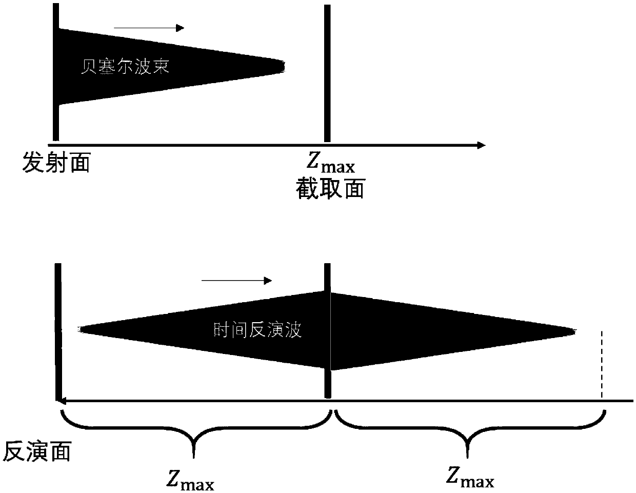
[0054] Such as Figure 1-5 As shown, a non-diffraction Bessel beam generation method based on time reversal includes the following steps:

[0055] Step 1: According to the electric and magnetic field distribution of Bessel waves, select a section as the initial wave emission surface, obtain the initial wave emission surface field distribution, and calculate the maximum non-diffraction distance of the initial wave according to the field distribution;

[0056] The maximum non-diffraction distance in step 1 is calculated as follows:

[0057]

[0058] Where ρ 0 Is the radius of the initial wave emitting surface, δ is the axicon angle of the initial wave beam, k ρ Is the radial wave number of electromagnetic wave, k z Is the axial wave number of the electromagnetic wave.

[0059] Step 2: Launch the initial wave to make it propagate in free space, and intercept the electric field at the maximum non-diffraction distance to obtain the electric field value at each position of the initial wave e...

Embodiment 2

[0074] Based on Example 1, the area of ​​the electric field intercepted in step 2 is larger than the area of ​​the initial wave launching surface, avoiding the shortcomings of traditional time inversion that the multipath information is not obvious, improving the integrity of the obtained field information, and further improving the accuracy of the traceback waveform ; At the same time, time reversal can also compensate and restore information. Because time reversal has the nature of space-time synchronous focusing, when the inverted Bessel wave passes through the same propagation area, the energy will be concentrated in the original position, thus reducing the sidelobe Energy decay speed, maintain a better waveform state, and improve the accuracy of the trace back waveform.


PUM


Abstract

The invention discloses a method for generating a non-diffraction Bessel wave based on time inversion and relates to the field of electromagnetic beamforming. The method comprises a step 1 of selecting a cross section as an initial wave emission surface according to the electric field and magnetic field distribution of the Bessel wave, obtaining the initial wave emission surface field distributionand calculating the maximum non-diffraction distance of the initial wave according to the field distribution; a step 2 of emitting the initial wave to propagate the initial wave in a free space, andintercepting an electric field at the maximum non-diffraction distance to obtain electric field values at various positions of the initial wave emission surface; and a step 3 of performing, after theelectric field value of the initial wave emission surface is discretized, a time inversion operation to obtain an inversion Bessel wave, emitting the inversion Bessel wave to propagate the inversion Bessel wave in the same free space and to generate a non-diffraction Bessel wave. The method solves the problem that the existing non-diffraction distance of the Bessel wave generated in the microwavefrequency band is short, and achieves an effect of greatly increasing the non-diffraction distance of the Bessel wave field.

Description

Technical field [0001] The invention relates to the field of electromagnetic wave beam forming, in particular to a method for generating a non-diffraction Bessel wave beam based on time inversion. Background technique [0002] Wave diffraction is a common physical phenomenon in nature. Diffraction occurs when electromagnetic waves propagate in space. The energy of electromagnetic waves will diffuse in space. Wave diffraction has an impact on all traditional wave fields. In many areas of microwave applications, such as long-distance wireless energy transmission and high-resolution imaging, it is necessary to suppress wave diffraction. Therefore, a non-diffraction electromagnetic beam is required, that is, the intensity of the field along the propagation direction does not change, and the wireless energy transmission is improved. Efficiency and resolution of far-field detection. [0003] The Bessel beam has the characteristics of spotlight propagation. It can travel long distances i...

Claims


Application Information

Patent Timeline
Patent Type & Authority Applications(China)
IPC IPC(8): H01Q3/26H01Q3/00H02J50/20
CPCH01Q3/00H01Q3/26H02J50/20
Inventor 董惠斌丁帅
Owner UNIV OF ELECTRONICS SCI & TECH OF CHINA
Why Eureka
Try Eureka