A method of making an aspheric surface
A technology of aspheric surface and aspheric lens, which is applied in the direction of manufacturing tools, instruments, lenses, etc., can solve the problems of complex processing technology, high risk, and difficulty in achieving collimation effect
- Summary
- Abstract
- Description
- Claims
- Application Information
AI Technical Summary
Problems solved by technology
Method used
Image
Examples
Embodiment 1
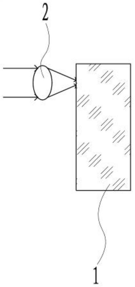
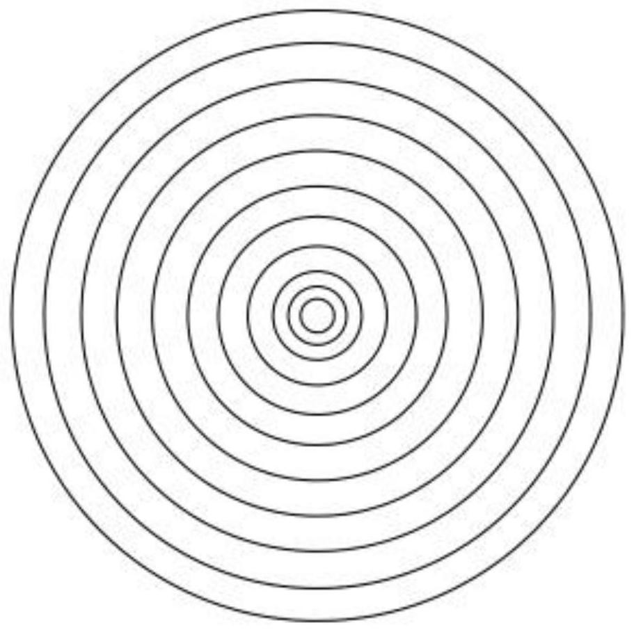
[0020] Such as figure 1 As shown, a method for making an aspheric surface uses a femtosecond laser 2 to irradiate an optical flat sheet 1 with femtosecond laser, and adjusts the energy density or beam waist diameter, irradiation trajectory and running speed of the femtosecond laser to make The refractive index distribution of the optical flat sheet changes, and the △n*H (optical path) changes in different regions are realized through the thickness H of the optical flat sheet and the femtosecond laser irradiation, so that the effect of the optical flat sheet 1 combined with the ordinary lens reaches Such as image 3 The aspheric effect of the aspheric lens in the prior art is shown, wherein the femtosecond laser irradiation trajectory of the optical flat plate 1 located on the end face of the same side is concentric along the central position of the irradiated end face and gradually progresses toward the edge of the irradiated end face Continuous femtosecond laser irradiation,...
Embodiment 2
[0022] Such as Figure 4 As shown, in this embodiment, the method for producing an aspheric surface in Example 1 is applied to the production of a three-piece structure composite aspheric lens, which includes a first lens 1 and an optical flat plate 2 arranged in sequence along the propagation direction of the optical path. and the second lens 3, the optical flat sheet 2 is irradiated with femtosecond laser by a femtosecond laser, so that the refractive index distribution of the optical flat sheet 2 is changed, so that the first lens 1, the optical flat sheet 2 and the second lens 3 are formed The three-piece composite lens achieves the effect of an aspheric lens.
Embodiment 3
[0024] Such as Figure 5 As shown, in this embodiment, the method for producing an aspheric surface in Example 1 is applied to the production of an aspheric cylindrical lens, which includes a first lens 1, an optical flat plate 2 and a second lens arranged in sequence along the propagation direction of the optical path 3. Femtosecond laser irradiation is performed on the optical flat sheet 2 by a femtosecond laser, so that the refractive index distribution of the optical flat sheet 2 is changed, and it is made into a long strip-shaped cylindrical surface compensation sheet, which changes the traditional cylindrical surface that is difficult to obtain ideal, The defects of the collimated optical effect make the first lens 1, the optical flat plate 2 and the second lens 3 constitute an aspheric cylindrical lens, which is used for cylindrical compensation with a large divergence angle of LD, that is, θ=±45°, which can be Get the desired effect.
PUM
 Abstract
Description
Claims
Application Information
 - R&D
- Intellectual Property
- Life Sciences
- Materials
- Tech Scout
- Unparalleled Data Quality
- Higher Quality Content
- 60% Fewer Hallucinations
Browse by: Latest US Patents, China's latest patents, Technical Efficacy Thesaurus, Application Domain, Technology Topic, Popular Technical Reports.
© 2025 PatSnap. All rights reserved.Legal|Privacy policy|Modern Slavery Act Transparency Statement|Sitemap|About US| Contact US: help@patsnap.com


