Clamping device used for internal gear machining

A clamping device and internal gear technology, applied in positioning devices, metal processing equipment, metal processing machinery parts, etc., can solve the problems of loose clamping, sticking, and excessive waste, and achieve the effect of reducing vibration

Inactive Publication Date: 2019-04-09
HARBIN UNIV OF SCI & TECH
View PDF6 Cites 2 Cited by
  • Summary
  • Abstract
  • Description
  • Claims
  • Application Information

AI Technical Summary

Problems solved by technology

[0002] At present, fixtures are needed to process internal gears. The traditional fixtures are clamped by the pressure plate, positioned by the pads, and aligned on the end face, and manual locking and adjustment are required. If the locking is excessive, the machined surface of the gear will be damaged. If it is loose, it will cause the clamping not to be tight and affect the gear production; at the same time, when processing the internal gear, too much scrap is cut off. If it is not handled in time, it may stick to the processed parts, resulting in errors and affecting the processing of the internal gear. precision

Method used


Image

  • Clamping device used for internal gear machining
  • Clamping device used for internal gear machining
  • Clamping device used for internal gear machining

Examples


specific Embodiment approach 1

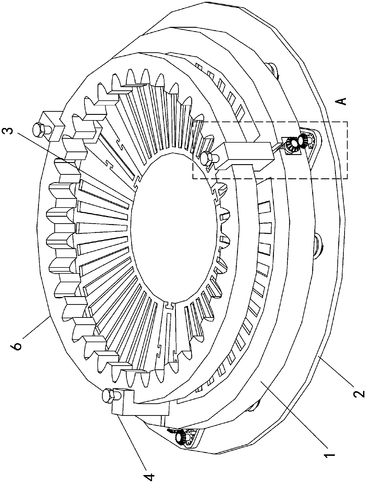
[0017] Specific implementation mode one: as Figure 1 to Figure 6 As shown, the present invention discloses a clamping device for processing internal gears, including a base 1, a base 2, a dust collector 3, three sets of clamping mechanisms 4 and a plurality of support columns 5;

[0018] The base 1 is a cylinder, and the three sets of clamping mechanisms 4 are equally divided along the circumferential direction of the base 1, and each set of clamping mechanisms 4 is horizontally slidably connected with the base 1. Three sets of clamping mechanisms 4 are used to fix the internal gear 6 to be processed. The end surface of the base 1 is provided with a through groove 1-1, and the inner side wall of the through groove 1-1 is vertically slidably connected with The dust suction device 3 is fixedly connected between the base 1 and the base 2 through a plurality of support columns 5 .

specific Embodiment approach 2

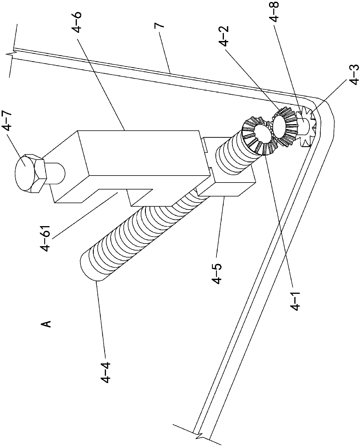
[0019] Specific implementation mode two: as Figure 2 ~ Figure 4 As shown, this embodiment is a further description of the first embodiment, the clamping device for internal gear processing also includes a chain 7 and a motor 8;

[0020] The clamping mechanism 4 described in each group all comprises bevel gear one 4-1, bevel gear two 4-2, sprocket wheel 4-3, threaded rod 4-4, slide block one 4-5, gear clamping block 4-6 , compression nut 4-7 and shaft rod 4-8;

[0021] The upper end surface of the base 1 is provided with three horizontal chute 1-2 equally divided along the circumferential direction, each of the horizontal chute 1-2 is slidably connected with a slider 4-5, each The upper ends of each of the first sliders 4-5 are fixed with gear clips 4-6, and the side walls of each of the gear clips 4-6 are provided with notches 4-61, and the three described three A notch 4-61 is used to place the internal gear 6 to be processed, and the upper end surface of each of the gear ...

specific Embodiment approach 3

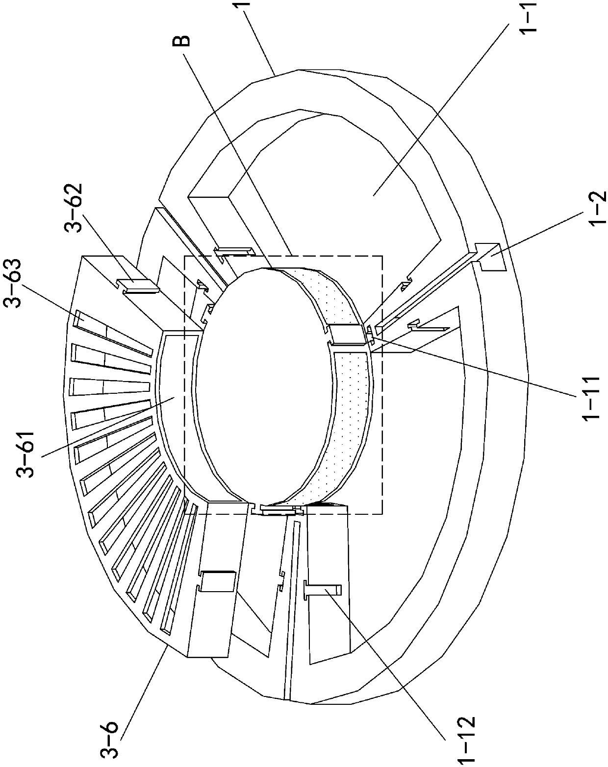
[0022] Specific implementation mode three: as image 3 , Figure 5 , Image 6 As shown, this embodiment is a further description of Embodiment 1. The dust collection device 3 includes a cylindrical box 3-1, a fan blade 3-2, a rotating shaft 3-3, an electric motor 3-4, and three A dust filter 3-5 and three dust collecting boxes 3-6;

[0023] Described rotating shaft one 3-3 is arranged in the cylindrical case 3-1, and the upper end of described rotating shaft one 3-3 is connected with the top plate of cylindrical case 3-1 by bearing three rotations, and the described rotating shaft one 3-3 The lower end is fixed with an electric motor 3-4, and the electric motor 3-4 is fixed on the bottom plate of the cylindrical box 3-1, and the outer side of the rotating shaft 3-3 is fixed with a fan blade 3-2, and the The cylindrical box 3-1 is slidingly connected with the inner side wall of the through groove 1-1 on the base 1, and the outer side wall of the cylindrical box 3-1 is provid...


PUM


Abstract

The invention discloses a clamping device used for internal gear machining and belongs to the technical field of gear machining auxiliary tools. A base is a cylinder. Three clamping mechanisms are uniformly arranged in the circumferential direction of the base. Each clamping mechanism is in sliding connection with the base. The three clamping mechanisms are used for fixing a to-be-machined internal gear. A through groove is formed in the end surface of the base. The inner side wall of the through groove is in sliding connection with a dust collecting device. The base is fixedly connected witha bottom seat through a plurality of supporting columns.

Description

technical field [0001] The invention relates to a gear clamping device, in particular to a clamping device for internal gear processing, and belongs to the technical field of gear processing auxiliary tools. Background technique [0002] At present, fixtures are needed to process internal gears. The traditional fixtures are clamped by the pressure plate, positioned by the pads, and aligned on the end face, and manual locking and adjustment are required. If the locking is excessive, the machined surface of the gear will be damaged. If it is loose, it will cause the clamping not to be tight and affect the gear production; at the same time, when processing the internal gear, too much scrap is cut off. If it is not handled in time, it may stick to the processed parts, resulting in errors and affecting the processing of the internal gear. precision. Contents of the invention [0003] The purpose of the present invention is to provide a clamping device for internal gear process...

Claims


Application Information

Patent Timeline
Patent Type & Authority Applications(China)
IPC IPC(8): B24B41/06B24B55/06B23Q3/06B23Q11/00
CPCB23Q3/06B23Q11/0046B24B41/06B24B55/06
Inventor 于广滨张元毛汉成
Owner HARBIN UNIV OF SCI & TECH
Why Eureka
Try Eureka