
Waste liquid collecting device for nephrology department

A waste liquid collection and internal medicine technology, which is applied in the field of nephrology waste liquid collection devices, can solve the problems of inconvenient installation and disassembly of waste liquid collection boxes, waste liquid splashing out, increased work difficulty, etc., to achieve easy cleaning and disinfection, and convenient removal of odors , Increase the effect of cushioning and shock absorption

Pending Publication Date: 2019-04-09
刘云芳
View PDF0 Cites 3 Cited by
  • Summary
  • Abstract
  • Description
  • Claims
  • Application Information

AI Technical Summary

Problems solved by technology

[0003] Existing medical waste is usually collected by a waste bag, and then the staff cuts the waste bag, etc., and then pours the waste into the sewer, and then throws the waste bag into the trash can, which is very easy to cause Secondary pollution, and the waste liquid contains a large odor, which increases the difficulty of this work, which is very troublesome, and the cost of some existing waste liquid collection devices is relatively high, and it is not convenient to install and disassemble the waste liquid collection box. As a result, it is not easy to clean, and its shock absorption effect is poor, which will easily cause the collection box to shake and the waste liquid to splash out. Therefore, we provide a waste liquid collection device for nephrology to solve this problem

Method used


Image

  • Waste liquid collecting device for nephrology department
  • Waste liquid collecting device for nephrology department
  • Waste liquid collecting device for nephrology department

Examples


Embodiment Construction

[0019] The technical solutions in the embodiments of the present invention will be clearly and completely described below in conjunction with the accompanying drawings in the embodiments of the present invention. Obviously, the described embodiments are only a part of the embodiments of the present invention, rather than all the embodiments.

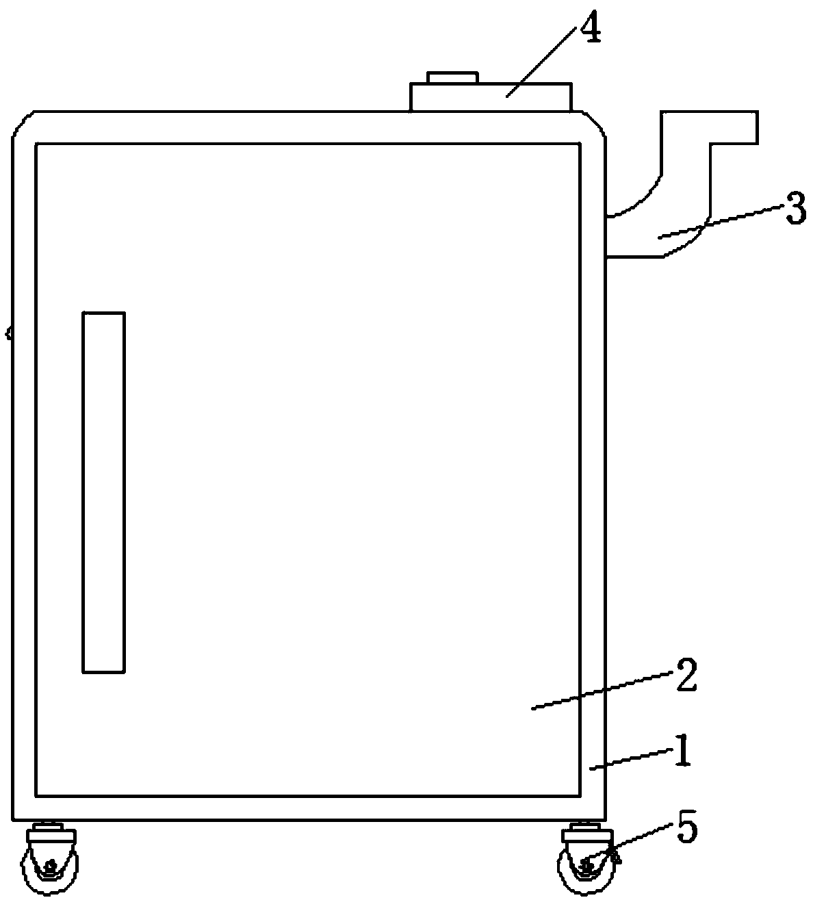
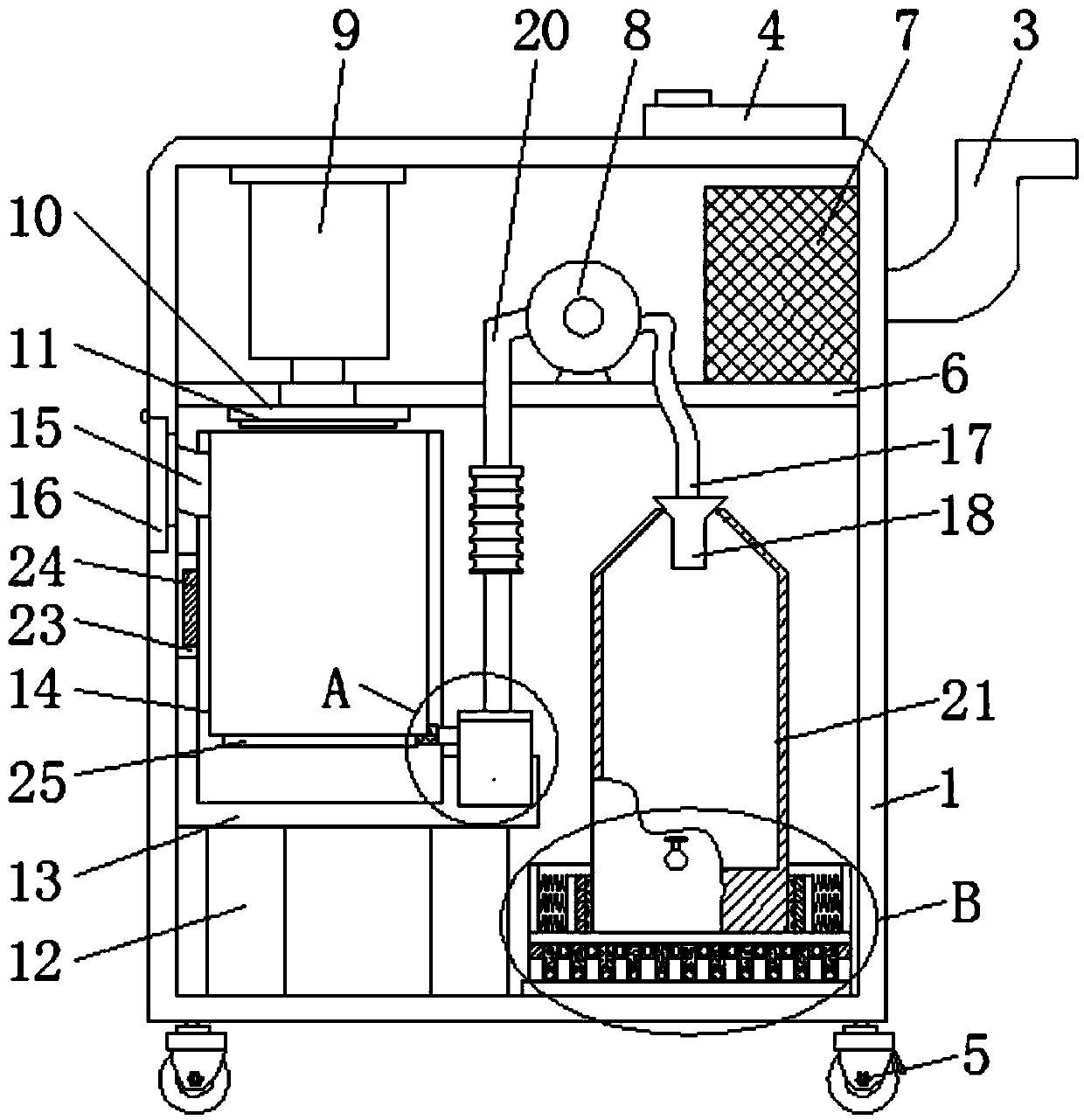
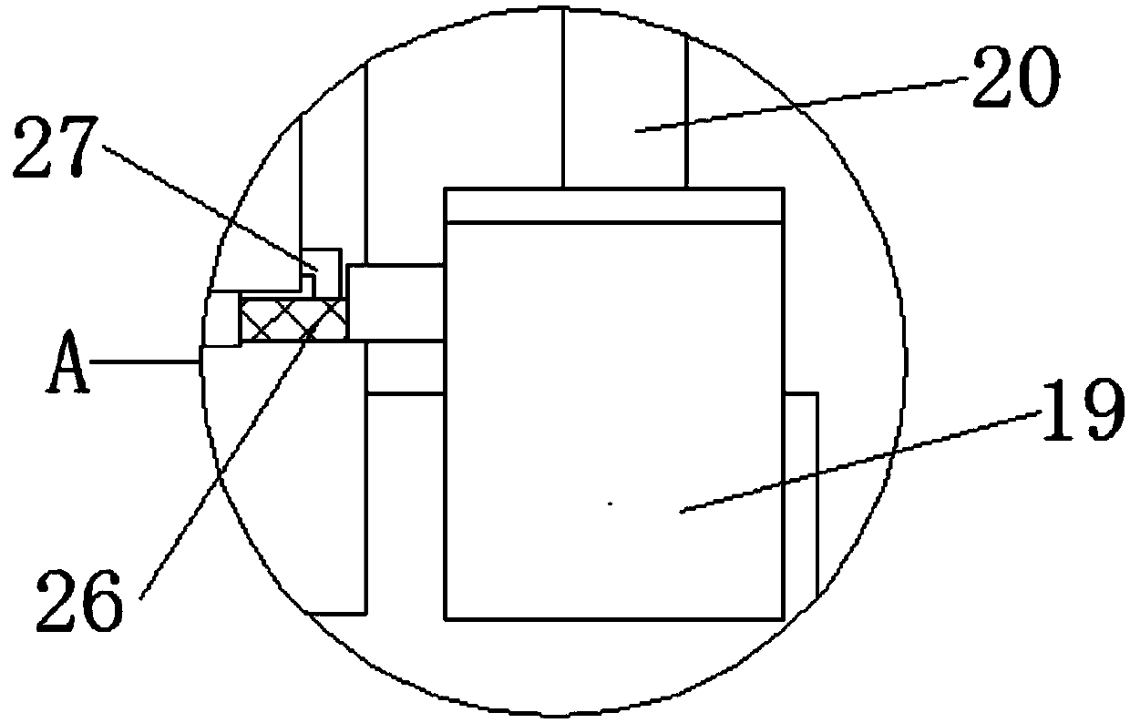
[0020] Reference Figure 1-4 , A nephrology waste liquid collection device, comprising a box body 1, a sealed door 2 is movably connected to the outside of the box body 1, a handle 3 is connected to the outside of the box body 1, and a control switch 4 is installed on the upper end of the box body 1. A universal wheel 5 is installed around the lower end of the body 1, a partition 6 is connected to the inner cavity of the box 1, a storage battery 7 is installed on the right side of the upper end of the partition 6, and a water pump 8 is installed in the middle of the upper end of the partition 6. The upper end of the inner cavity of the body...


PUM


Abstract

The invention relates to the technical field of waste liquid collection, in particular to a waste liquid collecting device for a nephrology department. The waste liquid collecting device comprises a box body, the outer side of the box body is movably connected with a sealing door, a handle is connected to the outer side of the box body, a control switch is arranged at the upper end of the box body, universal wheels are installed on the periphery of the lower end of the box body, a partition plate is connected to the inner cavity of the box body, a storage battery is installed on the right sideof the upper end of the partition plate, a water pump is installed in the middle of the upper end of the partition plate, an electric hydraulic cylinder is installed at the upper end of the inner cavity of the box body, the lower end of the electric hydraulic cylinder penetrates through the partition plate through a hydraulic rod and extends to the lower portion of the partition plate to be connected with a pressing plate, and the middle of the lower end of the pressing plate is connected with a cutter. The device has the advantages that the structure is simple, the design is reasonable, thepracticability is high, waste liquid can be effectively collected and treated conveniently, the collecting device can be installed and disassembled conveniently, the cleaning is convenient, and the buffering and damping effects on a collecting barrel are effectively improved.

Description

Technical field [0001] The invention relates to the technical field of waste liquid collection, in particular to a waste liquid collection device for nephrology. Background technique [0002] Kidney disease is a common and frequently-occurring disease. If it worsens, it can develop into uremia, which seriously endangers people's health. Chronic kidney disease has become another important disease threatening human health after cardiovascular and cerebrovascular diseases, tumors, and diabetes. It has become a global public health problem. Nephrology is a clinical department set up by hospitals at all levels to diagnose and treat kidney diseases. [0003] Existing medical waste liquid is usually collected by waste liquid bag, and then the waste liquid bag is cut and broken by the staff, and then the waste liquid is poured into the sewer, and then the waste liquid bag is thrown into the trash can, which is very easy to cause Secondary pollution, and the waste liquid contains a large p...

Claims


Application Information

Patent Timeline
IPC IPC(8): B65F1/14B65F1/16B65B69/00
CPCB65F1/1473B65B69/0008B65F1/14B65F1/16
Inventor 刘云芳
Owner 刘云芳
Learn More