A blast furnace burden surface imaging three-dimensional model reconstruction method and system

A blast furnace charge surface and 3D model technology, applied in the field of metallurgy, can solve the problems of the blast furnace charge surface height and surface shape, which are difficult to accurately measure the blast furnace charge surface imaging 3D model, to improve cloth information feedback, reduce image details, and reduce noise the effect of interference

Pending Publication Date: 2019-04-09
天津市三特电子有限公司
View PDF5 Cites 6 Cited by
  • Summary
  • Abstract
  • Description
  • Claims
  • Application Information

AI Technical Summary

Problems solved by technology

[0003] The purpose of the present invention is to provide a three-dimensional model reconstruction method for blast furnace charge level imaging that solves the technical problem that the current blast furnace charge level height and surface shape are difficult to accurately measure

Method used


Image

  • A blast furnace burden surface imaging three-dimensional model reconstruction method and system
  • A blast furnace burden surface imaging three-dimensional model reconstruction method and system
  • A blast furnace burden surface imaging three-dimensional model reconstruction method and system

Examples


Embodiment 1

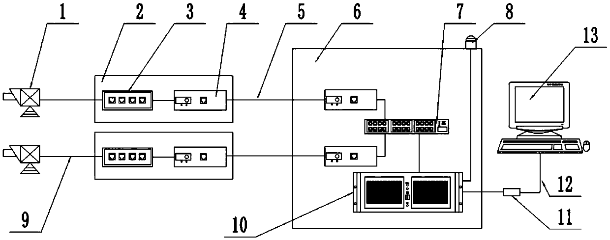
[0043] like figure 1 As shown, the three-dimensional model reconstruction system for blast furnace material level imaging includes two thermal imaging cameras 1 and an on-site control box 2 arranged on the site, as well as a control cabinet 6, an alarm 8 and a display 13 arranged in the control room;

[0044] Wherein, two thermal imaging cameras 1 are arranged on the horizontal direction and the vertical direction of the furnace wall of the blast furnace respectively, a pinhole lens is arranged at the front end of each thermal imaging camera 1, and a rotating device is connected at the rear end, and the rotating device is installed by The flange is fixed on the furnace wall of the blast furnace and forms a certain angle with the furnace wall of the blast furnace. Among them, the rotating device adopts the device in the published patent CN 201810478147. , so that the images in the furnace collected by the thermal imager completely cover the material surface in the furnace; each...

Embodiment 2

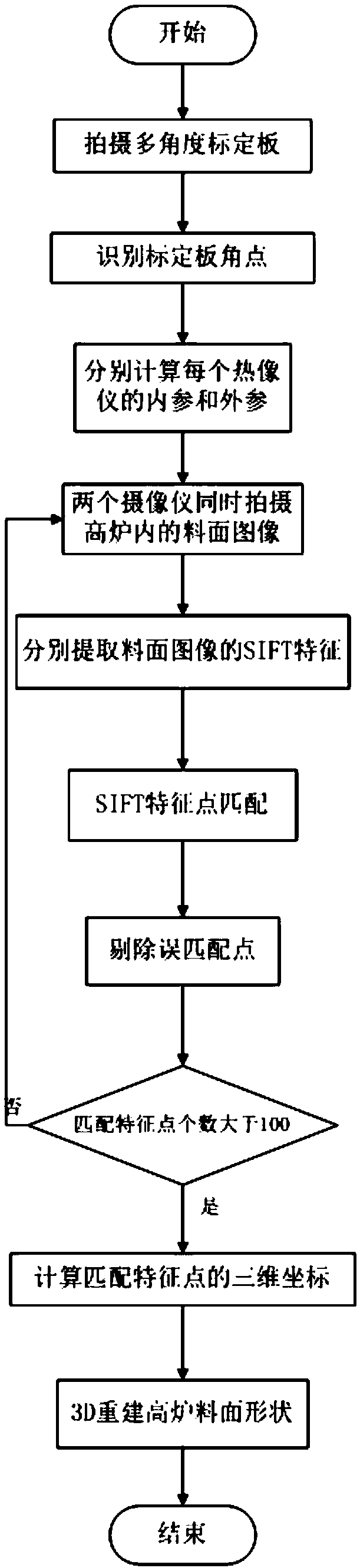
[0050] like figure 2 As shown, the specific implementation steps of the three-dimensional model reconstruction method for blast furnace charge level imaging realized by the above blast furnace charge level imaging three-dimensional model reconstruction system are as follows.

[0051] 1. Monitoring work preparation:

[0052] According to the structural layout of the real-time state monitoring system of the blast furnace charge level in Example 1, connect each system and debug the field control box and electrical cabinet to the normal working state, so that the power supply, electrical control, and data communication can work normally, and the pressure and temperature of the nitrogen cooling system Debug normal supply status;

[0053] Wherein, the outer air inlet provided on the rear side wall of the protective jacket and the inner air inlet provided on the side wall of the accommodating cavity are both connected to the cooling medium; specifically, the cooling medium adopts a...


PUM

PropertyMeasurementUnit
Overlap degreeaaaaaaaaaa

Abstract

The invention discloses a blast furnace burden surface three-dimensional model reconstruction method and system. The blast furnace burden surface three-dimensional model reconstruction system comprises at least two thermal imagers arranged in a blast furnace, an on-site control box positioned on site, and a control cabinet, an alarm and a display which are arranged in a control room; Wherein the two thermal imagers are arranged in the blast furnace at an interval in a manner that the installation angle is greater than or equal to 90 degrees, and the arrangement positions of any two thermal imagers meet the requirement that the acquisition range of infrared images has an overlapping rate greater than or equal to 50%; According to the system, basic matrixes of two thermal imagers are obtained through calibration of the double thermal imagers in sequence, matched matching feature point pairs of two on-line thermal imager images are extracted, and a point cloud model is formed by combiningthe basic matrixes and the feature point pairs of the double thermal imagers to achieve redrawing of a blast furnace burden surface three-dimensional image; According to the blast furnace burden surface three-dimensional model reconstruction method and system, observed blast furnace burden surface real information can form a three-dimensional image, the blast furnace burden surface real state iseffectively monitored in real time, and material distribution information feedback is greatly improved.

Description

technical field [0001] The invention relates to the technical field of metallurgy, in particular to a method and system for reconstructing a three-dimensional model of blast furnace material surface imaging. Background technique [0002] During the blast furnace material distribution process, the operator cannot directly observe information such as the 3D shape of the material surface in the blast furnace and the thickness of the material layer. In order to solve this problem, infrared thermal imaging technology and binocular vision technology in computer pattern recognition are used to analyze and process the material distribution information of the blast furnace, and to reproduce the three-dimensional image of the material surface in the process of material distribution, so as to accurately obtain material information. The height of each point on the surface can reflect the distribution of the material level in the blast furnace in real time, and realize the transparency a...

Claims


Application Information

Patent Timeline
Patent Type & Authority Applications(China)
IPC IPC(8): G06T17/00G06T7/33G06K9/46G06F17/16G01J5/00C21B5/00
CPCG06F17/16G06T7/337G06T7/344G06T17/00G01J5/0044C21B5/006G01J2005/0077G06T2207/10048G06V10/462
Inventor 张海根
Owner 天津市三特电子有限公司
Why Eureka
Try Eureka