Blast furnace charge level radar scanning 3D imaging device and monitoring system and monitoring method thereof

A blast furnace material surface and radar scanning technology, applied in the field of metallurgy, can solve problems such as inability to guarantee accuracy, incompatibility between temperature and material surface height, and difficulty in the distribution of material surface in the furnace.

Active Publication Date: 2016-08-24
天津市三特电子有限公司
View PDF3 Cites 10 Cited by
  • Summary
  • Abstract
  • Description
  • Claims
  • Application Information

AI Technical Summary

Problems solved by technology

However, since the above two methods have too few monitoring points, they cannot cover every point of the furnace top material surface, which makes it very difficult to analyze and grasp the distribution of the material surface in the furnace. The operator's experience can only be used to guess the material surface distribution of the blast furnace The state of airflow and airflow brings great randomness to the operation of the blast furnace, and the accuracy cannot be guaranteed, let alone the optimization of the material distribution operation;
[0006] Method 3 uses infrared imaging technology to analyze the infrar

Method used


Image

  • Blast furnace charge level radar scanning 3D imaging device and monitoring system and monitoring method thereof
  • Blast furnace charge level radar scanning 3D imaging device and monitoring system and monitoring method thereof
  • Blast furnace charge level radar scanning 3D imaging device and monitoring system and monitoring method thereof

Examples


Embodiment 1

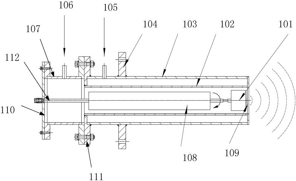
[0041] Such as figure 1 As shown, the 3D imaging device for blast furnace charge level radar scanning includes a microwave radar detector 101, a protective cover, an accommodating cavity 107, a rotating device 108 and a rear cover 110; wherein,

[0042] The protective cover includes a protective inner cover 102 and a protective outer cover 103. The protective outer cover 103 is arranged on the outside of the protective inner cover 102 in the form of a gap with the protective inner cover 102, and a ring end is arranged at the front end of the protective cover to be sealed and connected to the end face of the protective cover. Cover, a connecting flange 111 is arranged and fixed at the rear end of the protective jacket 103, and the flange cover of the connecting flange 111 is installed on the rear end face of the protective cover, so that the protective cover is formed into a closed annular structure with a center A sleeve body with through holes is formed; the microwave radar d...

Embodiment 2

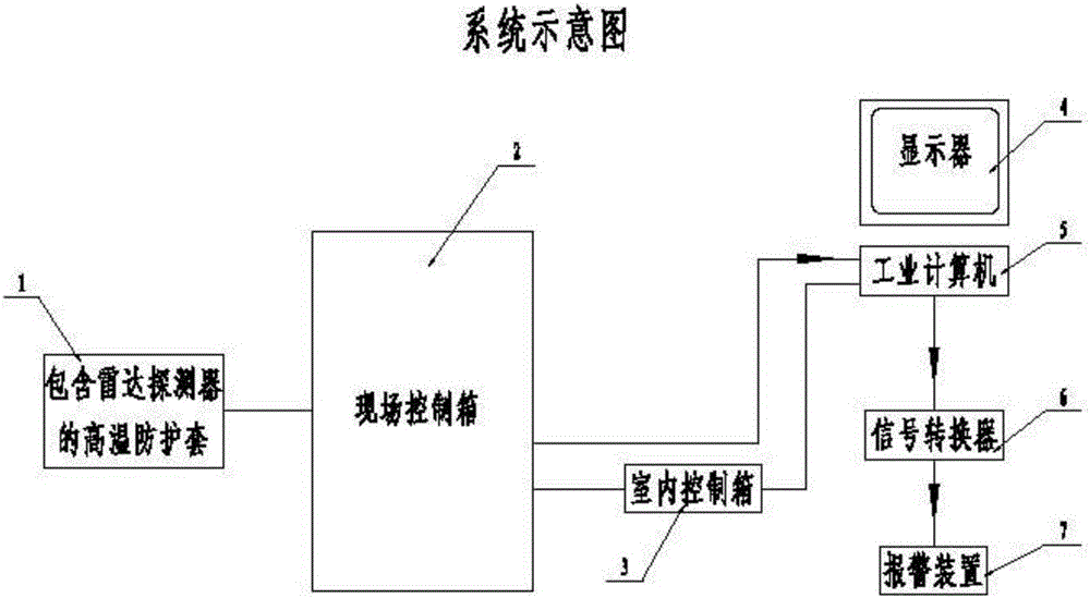
[0044] Such as image 3 As shown, a dynamic monitoring system for the shape of a blast furnace charge surface includes the blast furnace charge surface radar scanning 3D imaging device 1 described in Embodiment 1, a field control box 2, an indoor control box 3, a display 4, an industrial computer 5, and a signal converter 6 and alarm device 7; wherein:

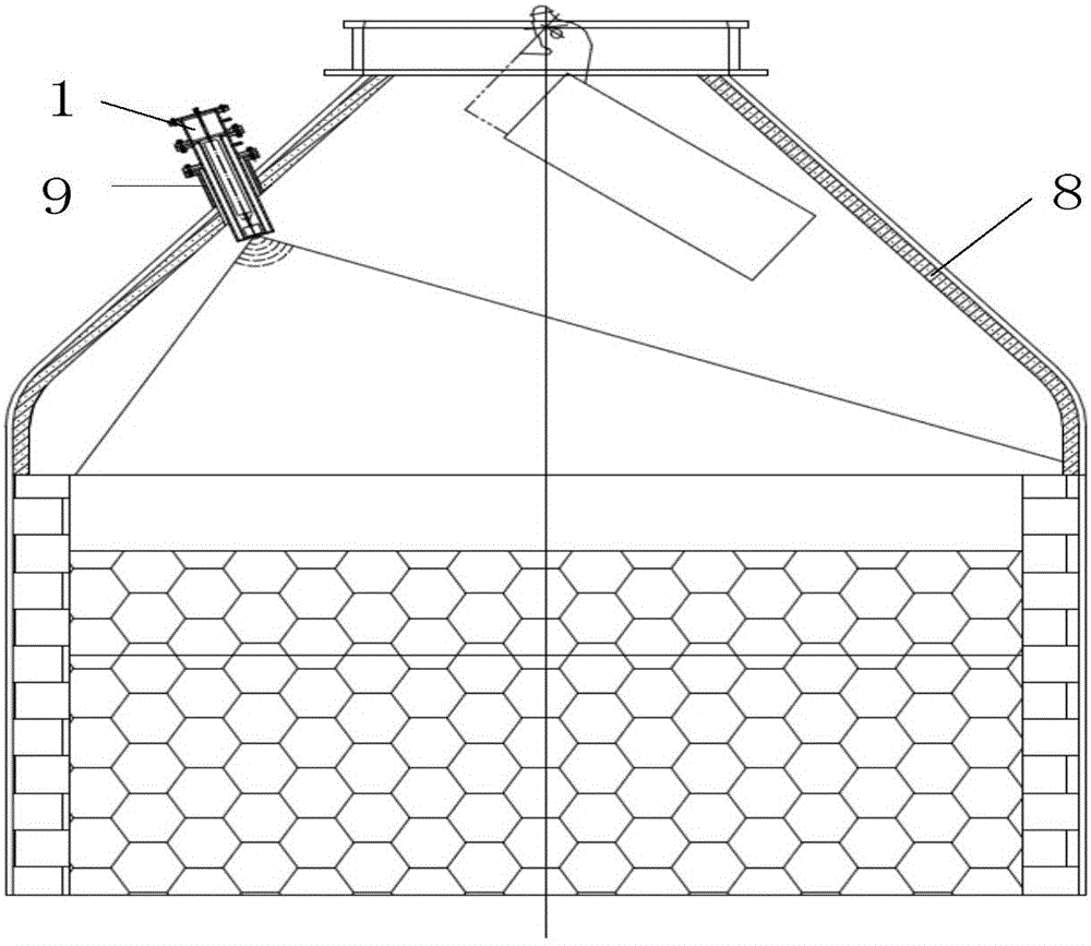
[0045] The blast furnace material level radar scanning 3D imaging device 1 is installed on the furnace wall above the blast furnace, such as figure 2 As shown, the installation angle between the imaging device 1 and the blast furnace wall is compatible with the internal structure of the blast furnace, ensuring that the scanning range of the microwave radar detector rotates 360° to cover the entire blast furnace material surface; Overlay scanning of all blast furnace material surfaces in the furnace;

[0046] The on-site control box 2 is set adjacent to the blast furnace, and the 3D imaging device 1 for radar scanning of the...

Embodiment 3

[0050] A method for real-time monitoring of the blast furnace charge level real-time state monitoring system using the blast furnace charge level shape dynamic monitoring system described in embodiment 2, comprising the following specific steps:

[0051] 1. Monitoring work preparation:

[0052] Connect each device according to the real-time state monitoring system structure of the blast furnace material surface, and debug the field control box and indoor control box to the normal working state, so that the power supply, electrical control, and data communication can work normally, and the pressure and temperature of the nitrogen cooling system can be adjusted to the normal supply state. ;

[0053] The outer layer air inlet 105 provided on the rear end side wall of the protective jacket 103 and the inner layer air inlet 106 provided on the side wall of the accommodating cavity 107 are both connected to the cooling medium; specifically, the cooling medium adopts a delivery press...


PUM


Abstract

The invention discloses a blast furnace charge level radar scanning 3D imaging device and a monitoring system and a monitoring method thereof. The imaging device is installed on a furnace wall on one side above a blast furnace; real blast furnace charge level scanning information of thousands of points is provided within several seconds through a most advanced radar probing technology and 360-degree holographic scanning; the real state of the blast furnace charge level is monitored in real time, and a charge level three-dimensional image is generated; by adopting the monitoring system and the monitoring method formed by the imaging device, the unsymmetrical material distribution state and the distribution of descending speeds of material charge levels can be detected online in real time, the material distribution information feedback is substantially improved, and technology analysis reaches a new altitude level; and to sum up, the blast furnace charge level radar scanning 3D imaging device and the monitoring system and the monitoring method thereof have the beneficial effects that real-time online detection precision is high and performance is stable, the technical problem that the height and the surface shape of the current blast furnace charge level cannot be accurately measured easily is solved, and optimized operation and reasonable material distribution are performed on the blast furnace.

Description

technical field [0001] The invention relates to the technical field of metallurgy, in particular to a blast furnace material level radar scanning 3D imaging device, a monitoring system and a monitoring method thereof. Background technique [0002] In the blast furnace ironmaking production process in the metallurgical industry, blast furnace material distribution is one of the most important links in the blast furnace ironmaking system. Accurate and effective grasp of the distribution of the material surface in the blast furnace is a prerequisite for ensuring the normal production and operation of the blast furnace and product quality. [0003] The measurement of blast furnace charge level has been a difficult problem for a long time. At present, there are roughly three methods for measuring the blast furnace charge level: [0004] Method 1. Traditionally, mechanical probes are used to collect data for monitoring the material level of closed blast furnaces. Each blast furn...

Claims


Application Information

Patent Timeline
IPC IPC(8): C21B7/24
CPCC21B7/24
Inventor 张海根
Owner 天津市三特电子有限公司
Why Eureka
Try Eureka