
Casting technology rapid verification method based on sand core 3D printing technology

A 3D printing and casting technology, applied in manufacturing tools, casting molding equipment, casting molds, etc., can solve the problems of long cycle, differences in thermophysical parameters, difficult on-site collection, etc., to improve work efficiency, improve accuracy, and compare The effect of reducing mold repair costs

Inactive Publication Date: 2019-04-12
SHANNXI DIESEL ENGINE HEAVY IND
View PDF5 Cites 6 Cited by
  • Summary
  • Abstract
  • Description
  • Claims
  • Application Information

AI Technical Summary

Problems solved by technology

To apply the traditional method to verify the casting process, it is first necessary to make a mold and carry out debugging and production. For some castings with complex structures and large wall thickness changes, it often requires multiple debugging, changing the casting process parameters, and modifying the mold. Due to the limitations of the mold, the traditional casting process requires Only one process plan can be verified at a time
Due to the long cycle and high cost required for casting mold making and modification, the cost and cycle of casting research and development stage are greatly increased
Although the casting process verification based on simulation technology is less costly and more efficient than traditional verification methods, because of the correlation between the simulation accuracy and the input material thermophysical parameters, there are differences in the thermophysical parameters of casting materials used by various foundry manufacturers, and It is not easy to collect on-site, resulting in low accuracy of simulation results, and finally needs to be verified in the commissioning and production stage

Method used

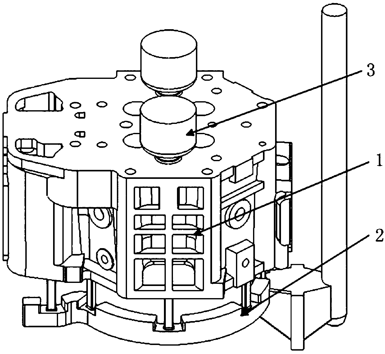
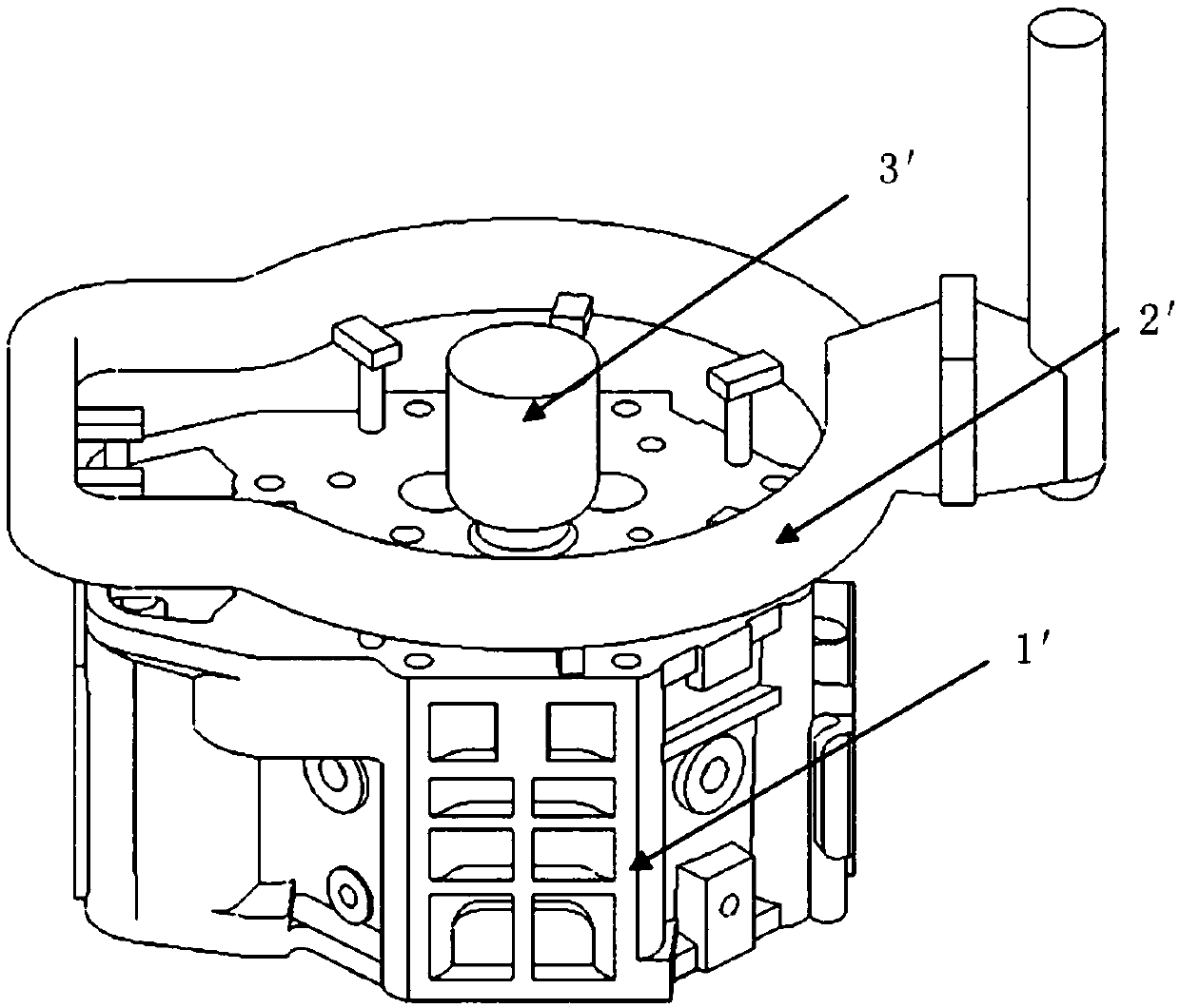

Image

  • Casting technology rapid verification method based on sand core 3D printing technology
  • Casting technology rapid verification method based on sand core 3D printing technology
  • Casting technology rapid verification method based on sand core 3D printing technology

Examples


Embodiment Construction

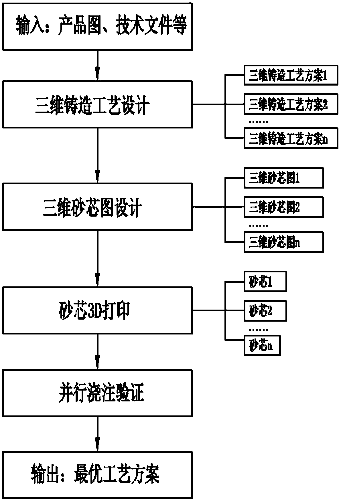
[0019] Attached below figure 1 Embodiments of the present invention are described.

[0020] A rapid verification method for casting process based on sand core 3D printing technology, such as figure 1 shown, including the following steps;

[0021] Step 1: Design of 3D casting process diagram: The design of 3D casting process diagram is different from the traditional planar 2D casting process design. In this invention, the input required for 3D printing of sand core is the 3D digital model of sand core, so it is necessary to carry out 3D casting process and sand core design. Therefore, in the stage of casting research and development or process improvement, it is first necessary to design and form a three-dimensional casting drawing according to the process parameters of the product part drawing, and then design and form a variety of three-dimensional casting process drawings according to the obtained three-dimensional casting drawing. Specifically, the three-dimensional cast...


PUM


Abstract

The invention provides a casting technology rapid verification method based on the sand core 3D printing technology. In the casting research and development or technology improvement stage, three-dimension casting technology drawings of different schemes are designed, three-dimension sand core drawings of different technology schemes are correspondingly designed, the sand core 3D printing technology is applied to produce sand cores of different technology schemes at the same time, finally, parallel actual pouring verification of the different technology schemes is conducted, and the optimal casting technology scheme is determined. According to the casting technology rapid verification method based on the sand core 3D printing technology, the sand core 3D printing technology is adopted formanufacturing the sand cores, the sand cores of different casting technologies can be rapidly produced under the situation that die manufacturing is not needed, and the purposes that the casting technology verification period is shortened, the technology verification cost is reduced, and the casting technology design accuracy is improved are achieved.

Description

technical field [0001] The invention belongs to the technical field of casting technology, and in particular relates to a rapid verification method of casting technology based on sand core 3D printing technology. Background technique [0002] Casting is a manufacturing process in which liquid metal smelted into a certain composition is injected into a mold cavity, and then cooled and solidified to obtain parts with the required shape and performance. It has many processes and a long production cycle. Casting process is the technology and method of producing castings by applying casting related theories and systematic knowledge, mainly including molding core making process, melting and pouring process, etc. It is the core link of casting production and one of the key factors determining the quality of castings. [0003] Casting process design is generally based on the experience of engineers, combined with relevant standards and manuals for parameter selection and design. Th...

Claims


Application Information

Patent Timeline
Patent Type & Authority Applications(China)
IPC IPC(8): B22C9/10B33Y80/00B33Y10/00
CPCB22C9/10B33Y10/00B33Y80/00
Inventor 郭敏刘彦付岳楼谷刚
Owner SHANNXI DIESEL ENGINE HEAVY IND
Learn More