Photo frame chamfering machine

A technology of chamfering machine and photo frame, which is applied in the direction of metal processing machine parts, clamping, support, etc. It can solve the problems of low surface roughness of chamfering, inaccurate clamping and positioning, and poor efficiency of chamfering in mass production. The roughness of the processed surface is low, the clamping is fast and accurate, and the effect of unevenness is avoided

Inactive Publication Date: 2019-04-12
COSCO W M J ALUMINUM DEV CO LTD
View PDF0 Cites 0 Cited by
  • Summary
  • Abstract
  • Description
  • Claims
  • Application Information

AI Technical Summary

Problems solved by technology

[0004] The purpose of the present invention is to overcome the shortcomings of the above-mentioned prior art, solve the problems of the prior art such as inaccurate clamping and positioning, poor efficiency of chamfering in batch production, and low roughness of the chamfering surface; provide a more convenient and applicable photo frame Chamfering machine, the photo frame chamfering machine can accurately clamp and position the workpiece and sense whether the work is placed accurately with only one pressing plate cylinder and left and right positioning bars. The different shapes of the splicing place can chamfer each side and each sharp corner of the photo frame at one time, and at the same time, it also eliminates the dislocation of the assembly at the splicing point of the frame

Method used


Image

  • Photo frame chamfering machine
  • Photo frame chamfering machine
  • Photo frame chamfering machine

Examples


Embodiment 1

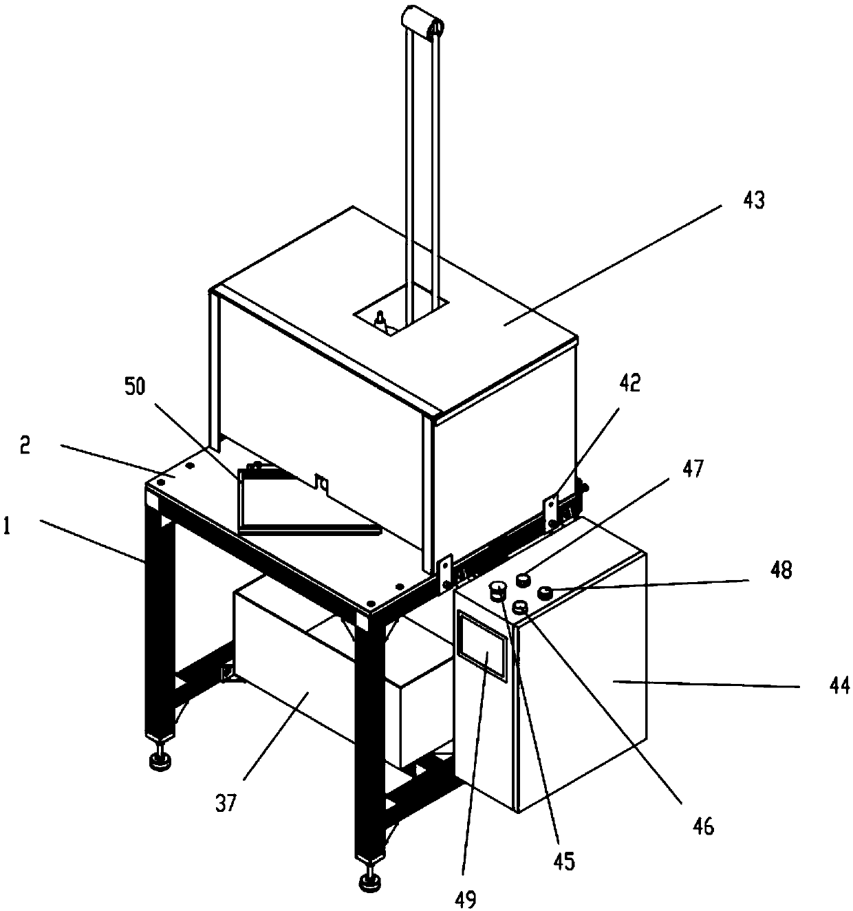
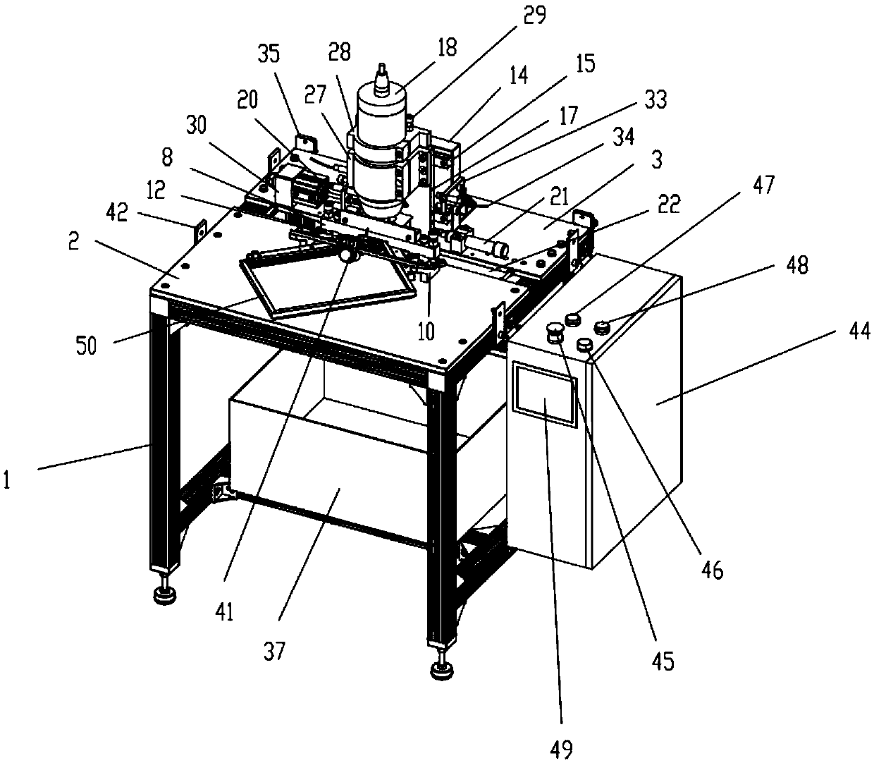
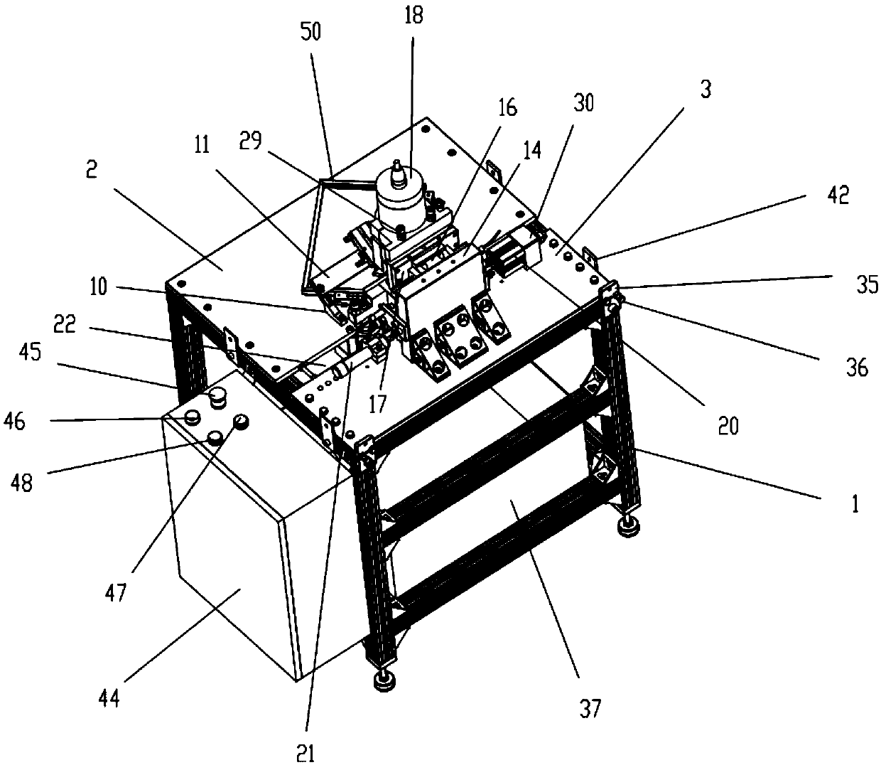
[0027] A kind of picture frame chamfering machine described in this embodiment 1, as figure 1 , figure 2 , image 3 , Figure 4 , Figure 5 , Figure 6 , Figure 7 , Figure 8 and Figure 9As shown, it includes a rack 1, a front panel 2 and a rear panel 3 arranged on the top platform of the rack, a left positioning bar 4 and a right positioning bar 5 arranged on the front panel at an angle greater than 90 degrees, and a left positioning bar Three magnetic induction type proximity switches 6 and two air nozzles 7 are provided on the inner side of the right positioning bar and the pressing plate 8 is located on the front panel and is positioned at the top of the left positioning bar and the right positioning bar. The pressing plate is connected with two pressing plate cylinders 9 that control the pressing down or resetting of the pressing plate, the oblique pressure cylinder fixing block 10 that is arranged on the front panel and located in front of the pressing plate, a...


PUM


Abstract

The invention discloses a photo frame chamfering machine. The photo frame chamfering machine can accurately locate and clamp a workpiece, whether the photo frame is placed in place or not does not need to be manually confirmed, a situation that the chamfering size of the photo frame is irregular can be avoided, the operation is simplified, and the machining efficiency is improved; a PLC is adoptedfor processing a magnetic induction type proximity switch and feedback signals of the proximity switch, an adopted clamping mode is unique and effective, the photo frame clamping is rapid and accurate, and a photo frame chamfer milling cutter can be used for machining chamfers at a sharp edge and a sharp corner of each spliced position of the photo frame at one time; and the workpiece needs onlyto be placed in the place roughly, the magnetic induction type proximity switch can control an oblique pressing weight to tightly press and clamp the workpiece after the induction type proximity switch senses the workpiece, the magnetic induction type proximity switch after clamping is used for detecting whether the photo frame is placed in the place again, then procedures of the dislocation pressing and the chamfer milling are automatically completed, and the milling and cutting size is stable. The speed of the photo frame chamfer milling cutter has two sections, wherein the idle motion speedis high and the milling and cutting motion speed is low, so that the efficiency is effectively improved and the roughness of the machined surface is low.

Description

technical field [0001] The invention relates to the technical field of mechanical processing equipment, in particular to a photo frame chamfering machine which can quickly chamfer the splicing sharp edges of a photo frame and can flatten the upper and lower dislocations assembled between each frame of the photo frame. Background technique [0002] The outer frame of the aluminum photo frame currently used on the market is assembled by the long and short frames with 45-degree angles on both sides through corner codes. After assembly, there are sharp corners at the joints of the long and short frames. In the mass production of photo frames, a special setting is required to remove these sharp corners, that is, chamfering; the processing methods of chamfering include milling and grinding. The grinding method requires frequent replacement of the grinding wheel or abrasive belt, the grinding speed and grinding flatness are not good, and the long sharp edge and the short sharp edge...

Claims


Application Information

Patent Timeline
Patent Type & Authority Applications(China)
IPC IPC(8): B23C3/00B23Q3/08B23Q5/00B23Q11/00B23Q17/00
CPCB23C3/00B23Q3/08B23Q5/00B23Q11/005B23Q17/00
Inventor 聂林强霍伟坚简亮
Owner COSCO W M J ALUMINUM DEV CO LTD
Why Eureka
Try Eureka