A multi-station CNC double-sided milling machine

A technology with a number of digits and double controls, applied in the field of milling machines, can solve the problems of inability to adjust the angle of the milling cutter, low work efficiency, high labor intensity, etc., and achieve the effect of avoiding manual transfer of parts, easy installation and disassembly, and convenient double-sided milling

Active Publication Date: 2020-01-24
山东欣畅模具科技有限公司
View PDF6 Cites 0 Cited by
  • Summary
  • Abstract
  • Description
  • Claims
  • Application Information

AI Technical Summary

Problems solved by technology

[0003] At present, when the existing milling machine mills a symmetrical plane for a part, it usually processes one side first, then manually reverses the direction of the part, and then processes the other side. To process multiple parts at the same time, the workers keep going up and down the workpiece, the labor intensity is high, and errors are prone to occur when manually turning the workpiece, the parallel accuracy of the two surfaces cannot meet the requirements, and the existing milling machine cannot adjust the angle of the milling cutter. Difficult to adapt to processing in different positions

Method used


Image

  • A multi-station CNC double-sided milling machine
  • A multi-station CNC double-sided milling machine
  • A multi-station CNC double-sided milling machine

Examples


Embodiment Construction

[0022] The following will clearly and completely describe the technical solutions in the embodiments of the present invention with reference to the accompanying drawings in the embodiments of the present invention. Obviously, the described embodiments are only some, not all, embodiments of the present invention. Based on the embodiments of the present invention, all other embodiments obtained by persons of ordinary skill in the art without making creative efforts belong to the protection scope of the present invention.

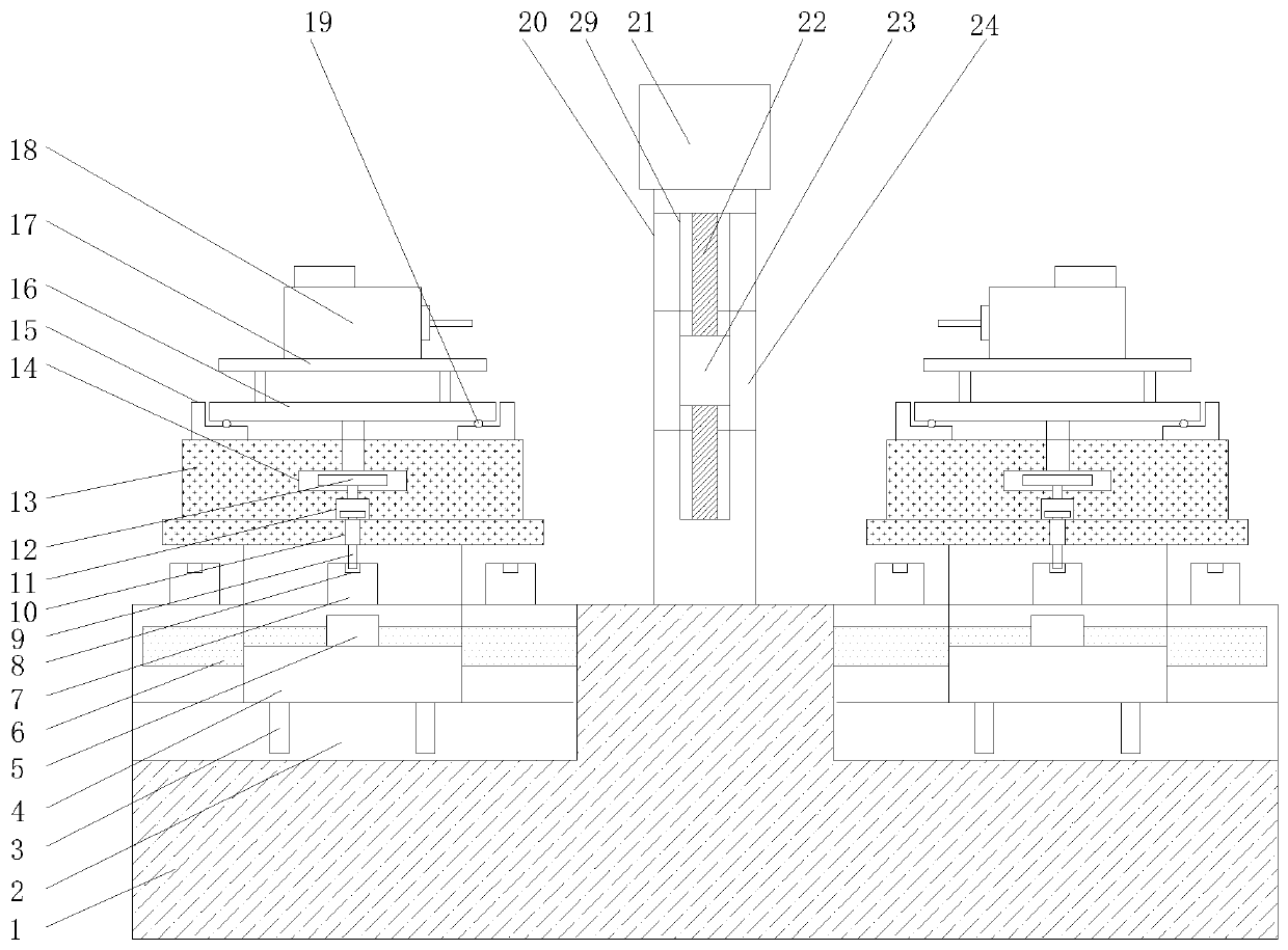
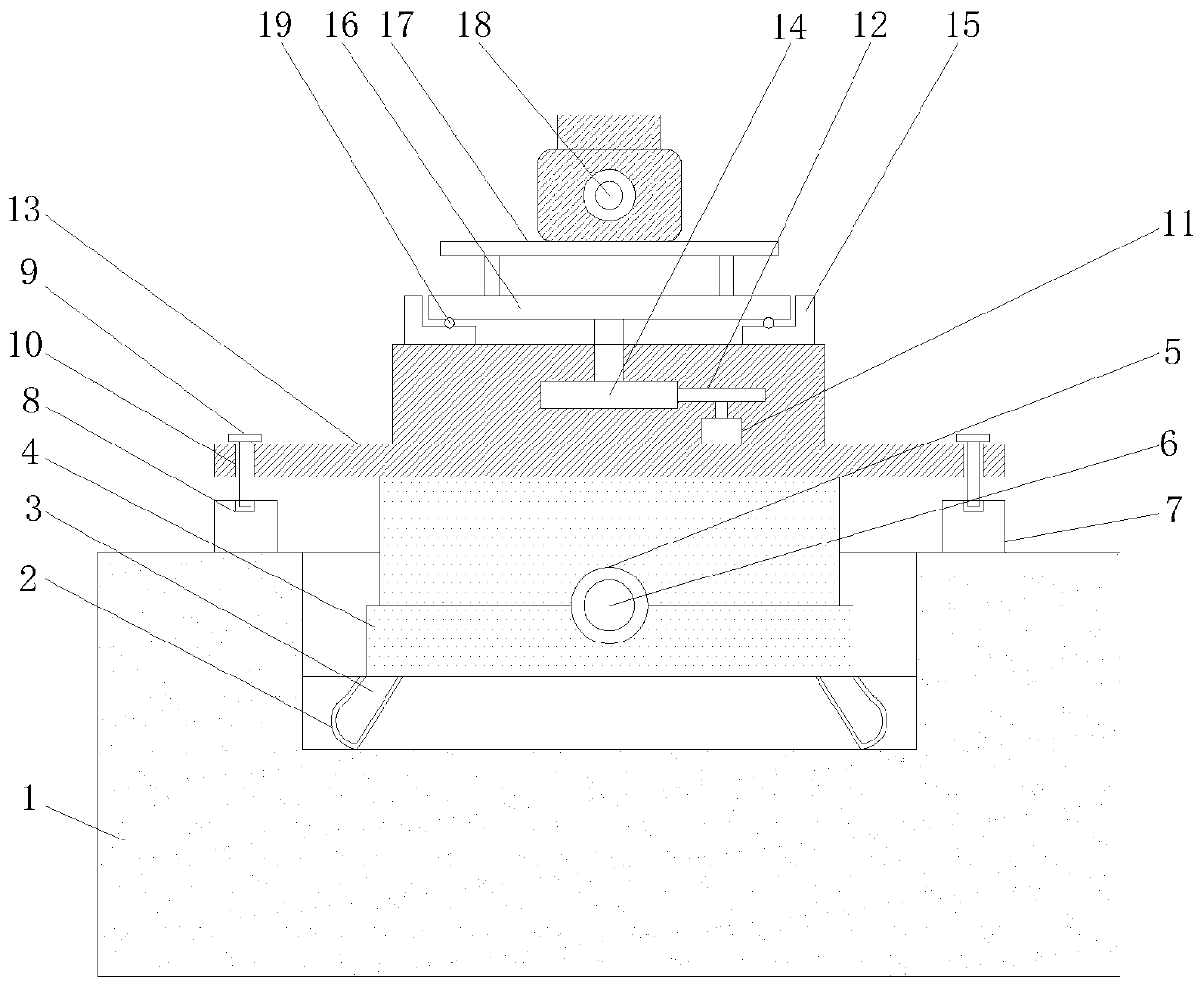
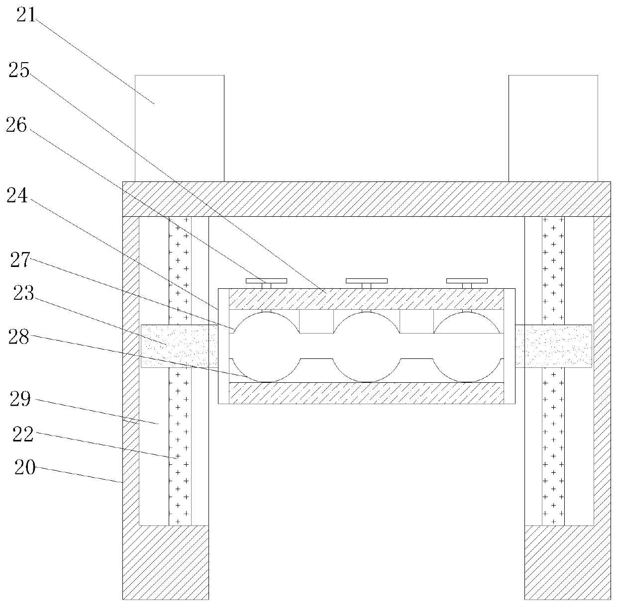
[0023] see Figure 1-3 As shown, a multi-station CNC double-sided milling machine includes a base 1 and a rotary positioning mechanism on the top of the base 1 for positioning the workpiece and a pressing moving mechanism for moving the workpiece;

[0024] The rotary positioning mechanism includes a chute 2, a slider 3, a fixed seat 4, a limit sleeve 5, a limit post 6, a limit block 7, a limit hole 8, a locking bolt 9, a positioning hole 10, a first motor 11....


PUM


Abstract

The invention belongs to the technical field of milling machines, and particularly relates to a multi-station numerical control double-side milling machine. The multi-station numerical control double-side milling machine comprises a base, a sliding groove, a sliding block, a fixing seat, a limiting sleeve, a limiting column, a limiting block, a limiting hole, a locking bolt, a positioning hole, afirst motor, a driving gear, a top seat, a driven gear, a rotating seat, a rotating disc, a fixing frame, a milling head driving motor, a ball, a supporting plate, a second motor, a lead screw, a leadscrew sliding table, connecting plates, a side plate, a fixing bolt, an upper clamping seat, a lower clamping seat and a limiting groove. According to the multi-station numerical control double-sidemilling machine, the structure is reasonable, the upper clamping seat at the bottom end of the fixing bolt moves downwards by rotating the fixing bolt, so that a to-be-machined part is fixedly connected between the upper clamping seat and the lower clamping seat, the lead screw is driven by the second motor to rotate, the lead screw drives the lead screw sliding table to move up and down, the leadscrew sliding table drives the to-be-machined part between the connecting plates to move up and down between the two supporting plates, so that the to-be-machined part is machined, manual turning ofthe part is avoided, errors are reduced, and machining precision is improved.

Description

technical field [0001] The invention belongs to the technical field of milling machines, in particular to a multi-station numerical control double-sided milling machine. Background technique [0002] A milling machine mainly refers to a machine tool that uses a milling cutter to process various surfaces of a workpiece. Usually, the milling cutter mainly uses rotational motion, and the movement of the workpiece and the milling cutter is a feed motion. It can process planes, grooves, and various Curved surfaces, gears, etc. In addition to milling planes, grooves, gear teeth, threads and spline shafts, milling machines can also process more complex profiles, with higher efficiency than planers, and are widely used in machinery manufacturing and repair departments. [0003] At present, when the existing milling machine mills a symmetrical plane for a part, it usually processes one side first, then manually reverses the direction of the part, and then processes the other side. Th...

Claims


Application Information

Patent Timeline
Patent Type & Authority Patents(China)
IPC IPC(8): B23C9/00B23C1/04B23Q3/06
CPCB23C1/04B23C9/00B23Q3/06
Inventor 不公告发明人
Owner 山东欣畅模具科技有限公司
Why Eureka
Try Eureka