A method of robot deburring based on 3D laser scanner

A technology of laser scanner and cleaning method, which is applied in the direction of machine tools suitable for grinding the edge of workpieces, parts of grinding machine tools, grinding/polishing equipment, etc., which can solve the problems of installation deviation, casting product scrapping, casting parting surface There are problems such as burrs, so as to reduce the clamping error and improve the product qualification rate

Active Publication Date: 2019-11-12
HUAZHONG UNIV OF SCI & TECH +2
View PDF7 Cites 0 Cited by
  • Summary
  • Abstract
  • Description
  • Claims
  • Application Information

AI Technical Summary

Problems solved by technology

[0003] However, the upper and lower molds of the casting mold have gaps on the joint surface, and the mold has been worn for a long time, and burrs appear on the parting surface of the casting
Using industrial robots to teach and program deburring, using a fixed program to control the robot obviously cannot meet the requirements. There are under-cut or over-cut phenomena in the deburring parts, resulting in the scrapping of castings. Due to the existence of burrs, castings are installed on the fixture with deviation. When robot deburring is used, the deviation value must be fed back to the robot control system to adjust the trajectory of the robot deburring program

Method used


Image

  • A method of robot deburring based on 3D laser scanner
  • A method of robot deburring based on 3D laser scanner
  • A method of robot deburring based on 3D laser scanner

Examples


Embodiment Construction

[0027] In order to make the object, technical solution and advantages of the present invention clearer, the present invention will be further described in detail below in conjunction with the accompanying drawings and embodiments. It should be understood that the specific embodiments described here are only used to explain the present invention, not to limit the present invention. In addition, the technical features involved in the various embodiments of the present invention described below can be combined with each other as long as they do not constitute a conflict with each other.

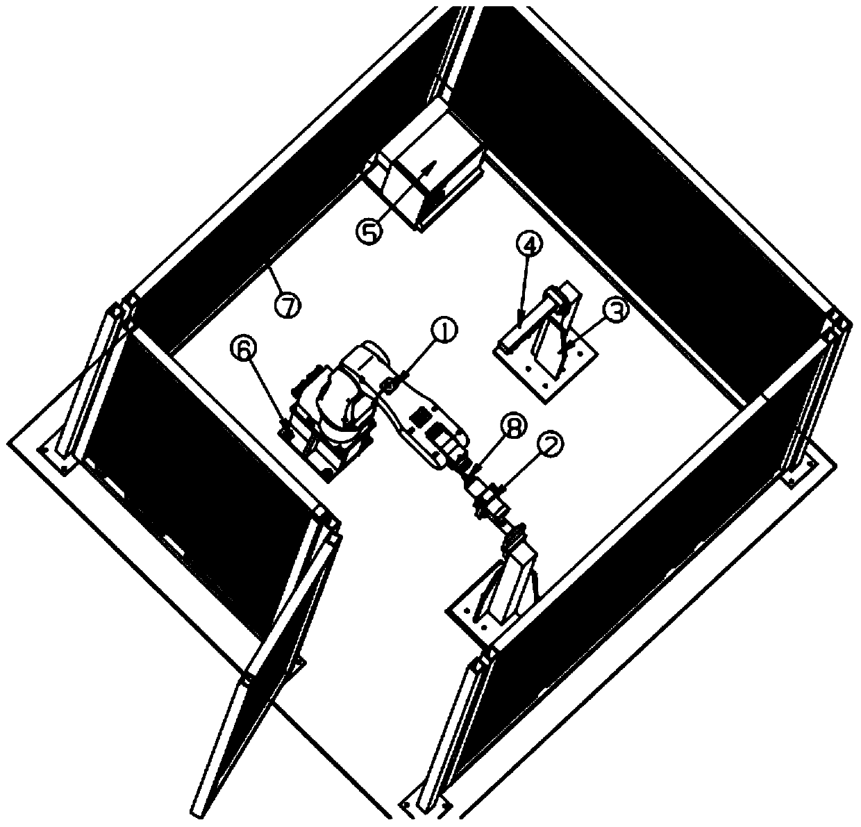
[0028] figure 1 It is a robot deburring system based on 3D laser scanner, such as figure 1 As shown, it includes an industrial robot system, a 3D laser scanner 4 and a high-speed electric spindle system, wherein the industrial robot system includes an industrial robot 1, a robot control cabinet 5 and a teaching box, and the industrial robot 1 is installed on the ground foundation through a fixe...


PUM


Abstract

The invention belongs to the field of automatic processing, and particularly discloses a robot deburring method based on a 3D laser scanner. The method comprises the following steps that a robot grabsa debugging workpiece to move in the visual field range of the 3D laser scanner according to a preset track to obtain a contour point cloud data Pri of the debugging workpiece; the debugging workpiece moves to the position of a tool for teaching programming to obtain a deburring track point coordinates Pj; a to-be-cleaned workpiece is grabbed to move in the visual field range of the 3D laser scanner to obtain a point cloud data Pwi of the to-be-cleaned workpiece in the same manner; the Pri and the Pwi are converted into a robot tail end coordinate system, and a position deviation matrix T andan attitude deviation matrix R are registered to obtain; the Pj is corrected by utilizing T and R, and the corrected deburring track point coordinates Pj' is obtained; and the robot clamps the to-be-cleaned workpiece to move relative to the tool to achieve deburring treatment according to the Pj'. The method has the advantages that the automation degree is high, the consistency of the parts afterdeburring is good, the deburring efficiency and the percent of pass are improved, and the pollution to the environment caused by the dust is reduced.

Description

technical field [0001] The invention belongs to the field of automatic processing, and more specifically relates to a method for cleaning robot burrs based on a 3D laser scanner. Background technique [0002] Casting products are widely used in the fields of automobiles, motorcycles, aerospace and construction machinery. After the parts are cast, they must be cleaned of burrs. The burrs of the castings not only affect the subsequent clamping of the workpiece, but also reduce the appearance quality of the parts. At present, Casting deburring is mainly carried out by hand-held pneumatic grinding head. Manual deburring not only has low efficiency, poor part consistency, high labor cost, but also causes great harm to the operator. Industrial robots have good flexibility, can meet workpieces of different sizes, have high processing efficiency, and low cost. Therefore, it is the future development trend to use industrial robots instead of manual deburring. [0003] However, there...

Claims


Application Information

Patent Timeline
Patent Type & Authority Patents(China)
IPC IPC(8): B24B9/00B24B1/00B24B51/00
CPCB24B1/00B24B9/00B24B51/00
Inventor 陈庚向华禹辉陈吉红林仁刚
Owner HUAZHONG UNIV OF SCI & TECH
Why Eureka
Try Eureka