
Vacuum evaporation device and vacuum evaporation method

An evaporation and vacuum technology, applied in vacuum evaporation plating, sputtering plating, ion implantation plating, etc., can solve the problems of reduced evaporation yield and poor adsorption effect of metal masks.

Inactive Publication Date: 2019-04-12
KUNSHAN GO VISIONOX OPTO ELECTRONICS CO LTD
View PDF9 Cites 1 Cited by
  • Summary
  • Abstract
  • Description
  • Claims
  • Application Information

AI Technical Summary

Problems solved by technology

[0003] However, during the use of the existing vacuum evaporation device, the magnetic plate does not have a good adsorption effect on the metal mask, which easily leads to a decrease in the evaporation yield.

Method used


Image

  • Vacuum evaporation device and vacuum evaporation method
  • Vacuum evaporation device and vacuum evaporation method
  • Vacuum evaporation device and vacuum evaporation method

Examples


Embodiment Construction

[0044] The present invention will be further described in detail below in conjunction with the accompanying drawings and embodiments. It should be understood that the specific embodiments described here are only used to explain the present invention, but not to limit the present invention. In addition, it should be noted that, for the convenience of description, only some structures related to the present invention are shown in the drawings but not all structures.

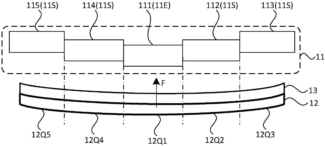
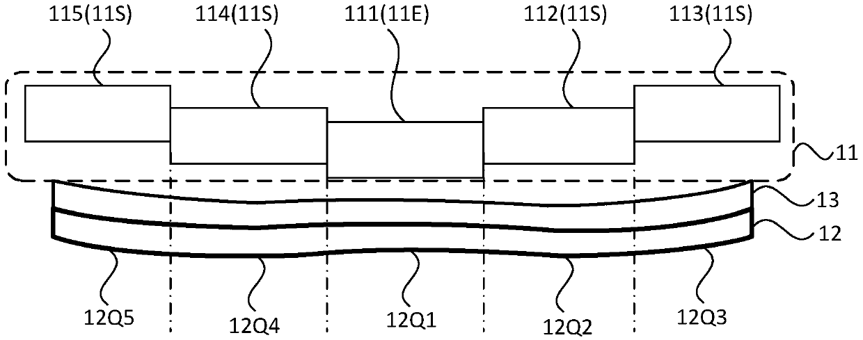
[0045] During the use of the vacuum evaporation device in the prior art, the magnetic plate used is generally a whole magnetic plate. During the adsorption process between the magnetic plate and the metal mask, due to the substrate placed above the metal mask Due to the gravity of the substrate itself, the substrate substrate sags and presses down on the metal mask. This situation will easily cause the central area of ​​the metal mask to sag, which will cause the surrounding edges of the metal mask to be closer to ...


PUM


Abstract

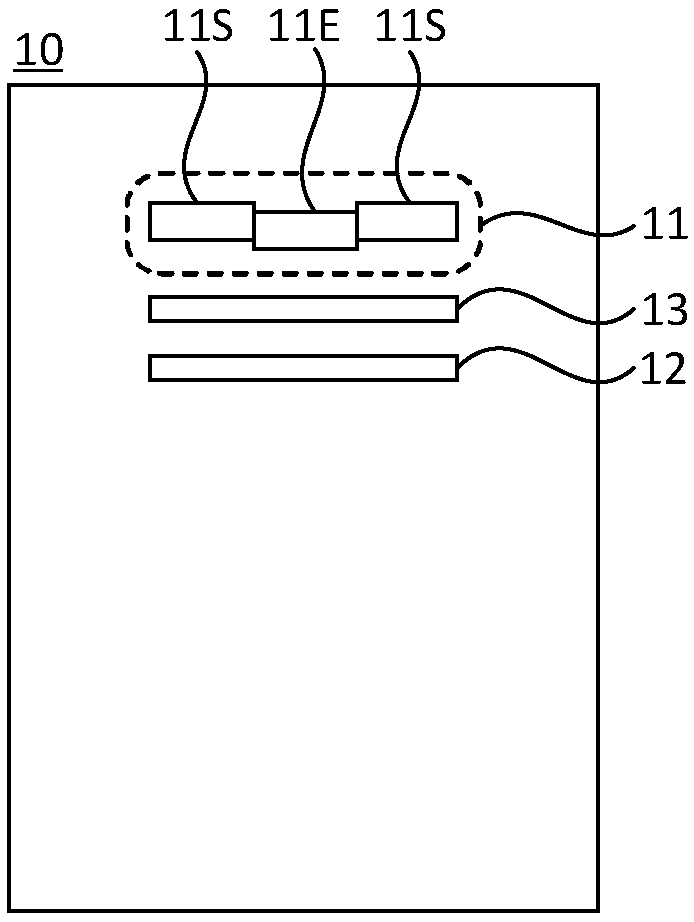
The embodiment of the invention discloses a vacuum evaporation device and a vacuum evaporation method. The vacuum evaporation device comprises a magnetic plate used for attracting a metal mask plate,the magnetic plate comprises a central magnetic plate unit and at least one peripheral magnetic plate unit located on the periphery of the central magnetic plate unit, wherein the central magnetic plate unit and the peripheral magnetic plate unit are independently and movably arranged relative to the metal mask plate. According to the technical scheme, the metal mask plate is sequentially attracted by utilizing the center magnetic plate unit and the peripheral magnetic plate unit which are independently arranged correspondingly, the flatness of the metal mask plate can be guaranteed, and therefore the evaporation yield can be improved.

Description

technical field [0001] The embodiments of the present invention relate to the technical field of display panel preparation, and in particular, to a vacuum evaporation device and a vacuum evaporation method. Background technique [0002] Organic Light-Emitting Diode (OLED) display device has become one of the main product directions of flat panel display technology due to its characteristics of self-luminescence, simple structure, easy realization of light and thin design, fast response speed, wide viewing angle and low power consumption. one. In the production process of organic light-emitting diodes, the organic light-emitting functional layer (including cathode, anode, electron transport layer, electron blocking layer, hole transport layer, hole blocking layer, organic light-emitting layer, or other functional film layers). In order to ensure good adhesion between the base substrate and the metal mask, a magnetic plate is usually provided on the side of the base substrat...

Claims


Application Information

Patent Timeline
IPC IPC(8): C23C14/24C23C14/04
CPCC23C14/042C23C14/24
Inventor 李文星李俊峰甘帅燕范波涛彭兆基
Owner KUNSHAN GO VISIONOX OPTO ELECTRONICS CO LTD
Learn More