Incinerator gas path structure

An incinerator and gas path technology, applied in the field of incinerators, can solve the problems of inability to deal with carbon monoxide, the heat of exhaust gas is not utilized, etc., and achieve the effects of adjustable heat dissipation, increased heat, and improved heat utilization.

Active Publication Date: 2020-04-10
浙江嘉策工程咨询有限公司
View PDF4 Cites 2 Cited by
  • Summary
  • Abstract
  • Description
  • Claims
  • Application Information

AI Technical Summary

Problems solved by technology

[0003] The first object of the present invention is to provide an incinerator gas circuit structure that can use tail gas to heat gaseous fuel to realize the utilization of tail gas heat, which solves the problem that the heat of the tail gas of the existing fuel furnace is not used
[0004] The second object of the present invention aims at further providing a kind of incinerator gas circuit structure that can make the carbon monoxide in the tail gas be removed on the basis of the first invention object, solves the problem that existing incinerators cannot handle the carbon monoxide in the tail gas The problem

Method used


Image

  • Incinerator gas path structure

Examples


Embodiment Construction

[0014] The present invention will be further described below in conjunction with the accompanying drawings and embodiments.

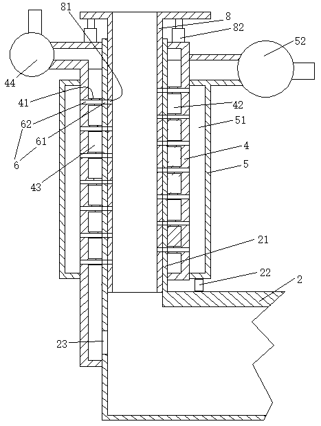
[0015] see figure 1 , an incinerator gas path structure, including an incinerator 2. The incinerator is provided with a chimney 21 , an air inlet 22 and a gaseous fuel inlet 23 . The chimney jacket is provided with a middle pipe 4 . The outer tube 5 is arranged on the outer tube of the middle tube. A fuel chamber 41 is formed between the middle pipe and the exhaust pipe. The fuel chamber is provided with a spiral guide piece 42 with the center line of the chimney as the center line. The spiral guide piece forms a spiral gas channel 43 in the fuel chamber. One end of the gas passage is connected with the gas fuel inlet, and the other end is connected with the outlet of the fuel delivery pump 44 . The part of the chimney inside the middle pipe is made of heat-conducting material. An air chamber 51 is formed between the outer tube and the middle tub...


PUM


Abstract

The invention relates to an incinerator gas path structure. The incinerator gas path structure comprises an incinerator; the incinerator is provided with a chimney, an air inlet port and a gas fuel inlet port; the chimney is sleeved with a middle pipe; the middle pipe is sleeved with an outer pipe; a fuel chamber is formed between the middle pipe and an exhaust gas discharge pipe; a screw guide piece is arranged in the fuel chamber; the spiral guide piece forms a spiral fuel gas channel in the fuel chamber; one end of the fuel gas channel is connected with the gas fuel inlet port, and the other end of the fuel gas channel is connected with an outlet of a fuel transfer pump; the part, located in the middle pipe, of the chimney is made of a heat conductive material; an air chamber is formedbetween the outer pipe and the middle pipe; one end of the air chamber is connected with the air inlet port; and the other end of the air chamber is connected with an outlet of an air blower. The incinerator gas path structure provided by the invention is capable of heating gas fuel through exhaust gas so that utilization of exhaust gas heat can be achieved, and the problem that heat of exhaust gas of existing fuel furnaces is not utilized is solved.

Description

technical field [0001] The invention relates to an incinerator, in particular to an incinerator gas path structure. Background technique [0002] The burning of objects is usually accomplished by an incinerator, such as burning wood, coal, etc. When the incinerator burns, it is completed by contacting the air with the burning substance (fuel) and then igniting it. The flue gas produced during combustion is discharged through the exhaust pipe. However, insufficient combustion often occurs during the combustion process, resulting in carbon monoxide contained in the tail gas being discharged along with the flue gas. The discharge of carbon monoxide not only wastes the fuel source but also causes air pollution caused by exhaust gas, and if it enters the room, it may cause carbon monoxide poisoning. In addition, the temperature of the tail gas discharged from the incinerator is relatively high, and the temperature that the bag that removes dust from the tail gas can withstand ...

Claims


Application Information

Patent Timeline
Patent Type & Authority Patents(China)
IPC IPC(8): F23G5/46F23G5/50
CPCF23G5/46F23G5/50F23G2206/10F23G2207/104
Inventor 钟国锋
Owner 浙江嘉策工程咨询有限公司
Why Eureka
Try Eureka