
All-optical information acquiring device and method based on four-zone phase delay array

A phase delay and acquisition device technology, which is applied in the field of all-optical information acquisition devices based on a four-zone phase delay array, can solve problems such as difficulty in real-time measurement, spectral aliasing, limited resolution and polarization measurement accuracy, and avoid Time and space mismatch problems, avoiding spectral aliasing, and the effect of good real-time performance

Active Publication Date: 2019-04-12
QINGDAO UNIV OF SCI & TECH
View PDF9 Cites 5 Cited by
  • Summary
  • Abstract
  • Description
  • Claims
  • Application Information

AI Technical Summary

Problems solved by technology

[0005] At present, the conventional measurement methods of Stokes vector spectrum in the world include time-sequence measurement and space-sequence measurement. The above methods all need to measure the target multiple times, and there are problems of time or space mismatch, which limit its resolution and polarization. Measurement accuracy; at the same time, it is difficult to achieve real-time measurement, which limits its application in the field of polarization detection
In 1999, Kazuhiko Oka et al. proposed a new method of intensity modulation to measure Stokes vector spectrum. This method can measure 4 Stokes parameters at the same time, has good real-time performance, and avoids the problem of time and space mismatch; but the channel modulation method will cause spectral resolution. At the same time, due to the unsolvable spectral aliasing problem between channels, there is an error in the restored Stokes vector, and in order to minimize the aliasing error, only the wide-band spectrum can be measured

Method used


Image

  • All-optical information acquiring device and method based on four-zone phase delay array
  • All-optical information acquiring device and method based on four-zone phase delay array
  • All-optical information acquiring device and method based on four-zone phase delay array

Examples


Embodiment Construction

[0043] The present invention will be described in further detail below in conjunction with the accompanying drawings and specific embodiments.

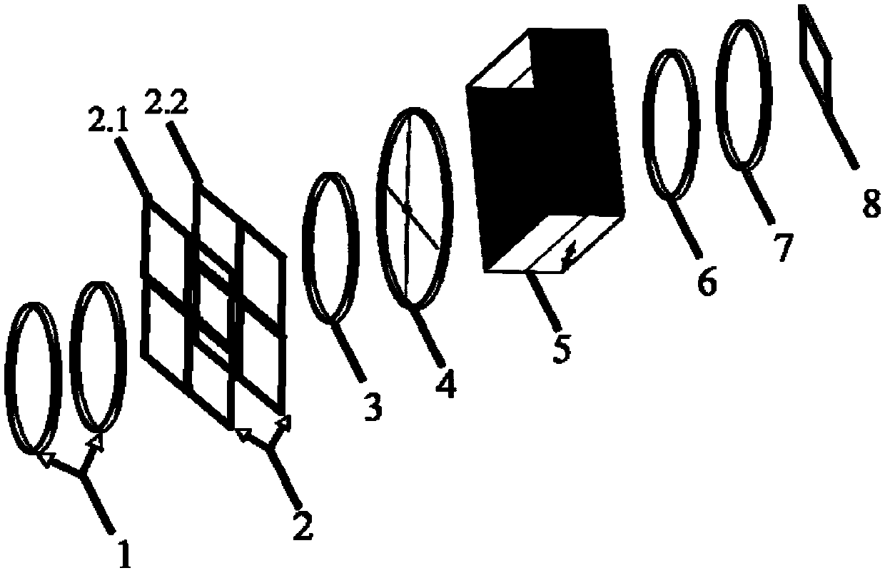
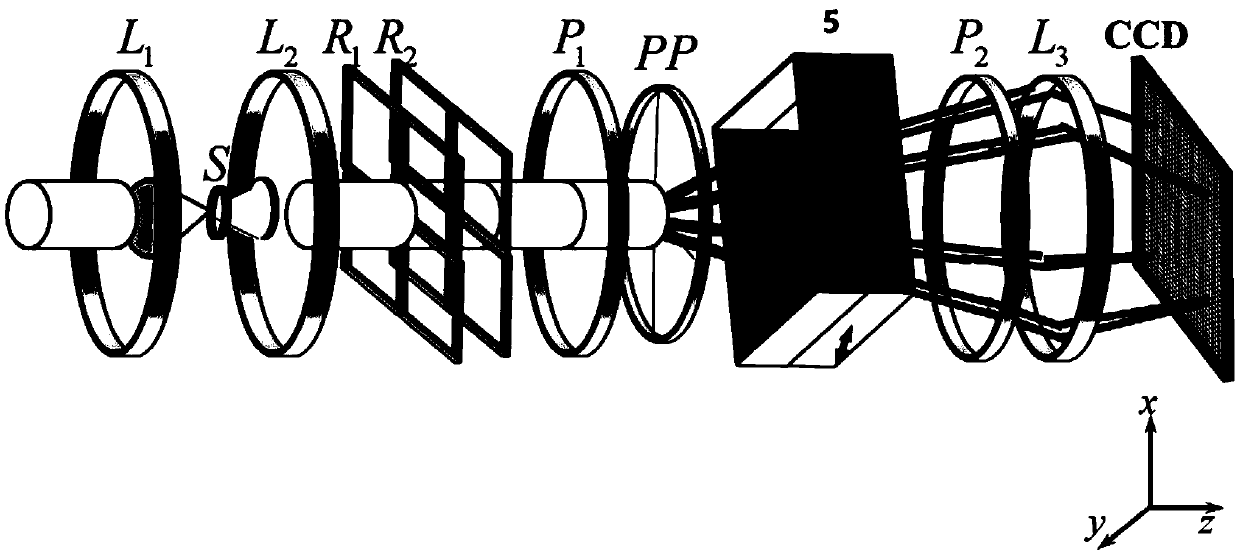
[0044] see figure 1 with figure 2 , a device for obtaining all-optical information by a four-section phase delay array of the present invention, comprising a front telescopic system 1, a four-section phase retarder assembly 2, a polarizer 3, a four-sided corner cube prism 4, a Savart polarizer 5, a detection It is composed of polarizer 6, imaging mirror 7 and CCD detector 8.

[0045] Construct an xyz coordinate system that satisfies the right-hand rule, and the main optical axis is the Z axis; among them, the front telescopic system is vertically set in the direction of the main optical axis of the incident light, and the four-part phase retarder component is located in the direction of the main optical axis The rear of the system consists of two sets of high-order delays, the first set of high-order delays R 1 The angle between t...


PUM


Abstract

The invention discloses an all-optical information acquiring device and method based on a four-zone phase delay array. The all-optical information acquiring device comprises a front telescoping system, a four-zone phase delayer assembly, a polarizer, a four-face pyramid prism, a Savart polariscope, a polarization analyzer, an image-forming mirror and a CCD detector. The front telescoping system, the four-zone phase delayer assembly, the polarizer, the four-face pyramid prism, the Savart polariscope, the polarization analyzer, the image-forming mirror and the CCD detector are sequentially arranged in the direction of a main light axis of incident light. An xyz coordinate system meeting the right-hand rule is established, and the main light axis is the Z axis. A first set of delayers is located between a second set of delayers and the front telescoping system, the included angle between the fast-axis direction of the first set of delayers and the x axis is 0 degree, and the included angle between the fast-axis direction of the second set of delayers and the forward direction of the x axis is 45 degrees. The all-optical information acquiring device can realize all-Stokes vector polarization information detection without causing reduction of the resolution, and has no special requirement for an incident spectrum.

Description

technical field [0001] The invention belongs to the field of imaging spectrum polarization, in particular to an all-optical information acquisition device and method based on a four-part phase delay array. Background technique [0002] As a new type of optical detection method, Imaging Spectropolarimetry (ISP) is currently carried out by only a few scientific research institutions in the world. In particular, Interference Imaging Spectropolarimetry (IISP) is still in the stage of principle exploration and experimental verification, and its technical means are not yet mature. [0003] Polarization interference imaging spectroscopy technology is a new type of optical remote sensing detection technology developed on the basis of polarization interference technology and spatial modulation interference imaging spectroscopy technology that appeared internationally in the late 1990s, using birefringent crystals as spectroscopic components. The depth and development of spatial modu...

Claims


Application Information

Patent Timeline
Patent Type & Authority Applications(China)
IPC IPC(8): G01J3/45
CPCG01J3/45
Inventor 高鹏艾晶晶郭广海张帅一滕利华胡晓晨
Owner QINGDAO UNIV OF SCI & TECH
Learn More