
Negative photoresist material and color filter

A kind of negative photoresist and pigment technology, applied in the direction of filter, photosensitive material for opto-mechanical equipment, optics, etc., can solve the problems of dark state light leakage, affecting the liquid crystal inversion, and the position of the overlap cannot be completely flat. , to avoid light leakage and reduce horns

Active Publication Date: 2019-04-12
TCL CHINA STAR OPTOELECTRONICS TECH CO LTD
View PDF4 Cites 8 Cited by
  • Summary
  • Abstract
  • Description
  • Claims
  • Application Information

AI Technical Summary

Problems solved by technology

[0004] The invention provides a negative photoresist material and a color filter to solve the existing color filter, because there is overlap between the color color resists, and between the color color resists and the black matrix, and the position of the overlap It cannot be completely flat to form a horn with a certain height. However, due to the limitation of the manufacturing process in design, the horn cannot be optimized. If the horn is too high, it will affect the inversion of the liquid crystal after the box is formed, causing light leakage in the dark state, and then affecting the display. technical problem

Method used


Image

  • Negative photoresist material and color filter
  • Negative photoresist material and color filter
  • Negative photoresist material and color filter

Examples


Embodiment Construction

[0021] The following descriptions of the various embodiments refer to the accompanying drawings to illustrate specific embodiments in which the invention may be practiced. The directional terms mentioned in the present invention, such as [top], [bottom], [front], [back], [left], [right], [inside], [outside], [side], etc., are only for reference The orientation of the attached schema. Therefore, the directional terms used are used to illustrate and understand the present invention, but not to limit the present invention. In the figures, structurally similar elements are denoted by the same reference numerals.

[0022] The present invention is aimed at the existing color filter, because there is overlapping between the color color resists and between the color color resists and the black matrix, and the overlapping position cannot be completely flat, forming a horn with a certain height, but in terms of design Due to the limitations of the manufacturing process, it is impossib...


PUM


Abstract

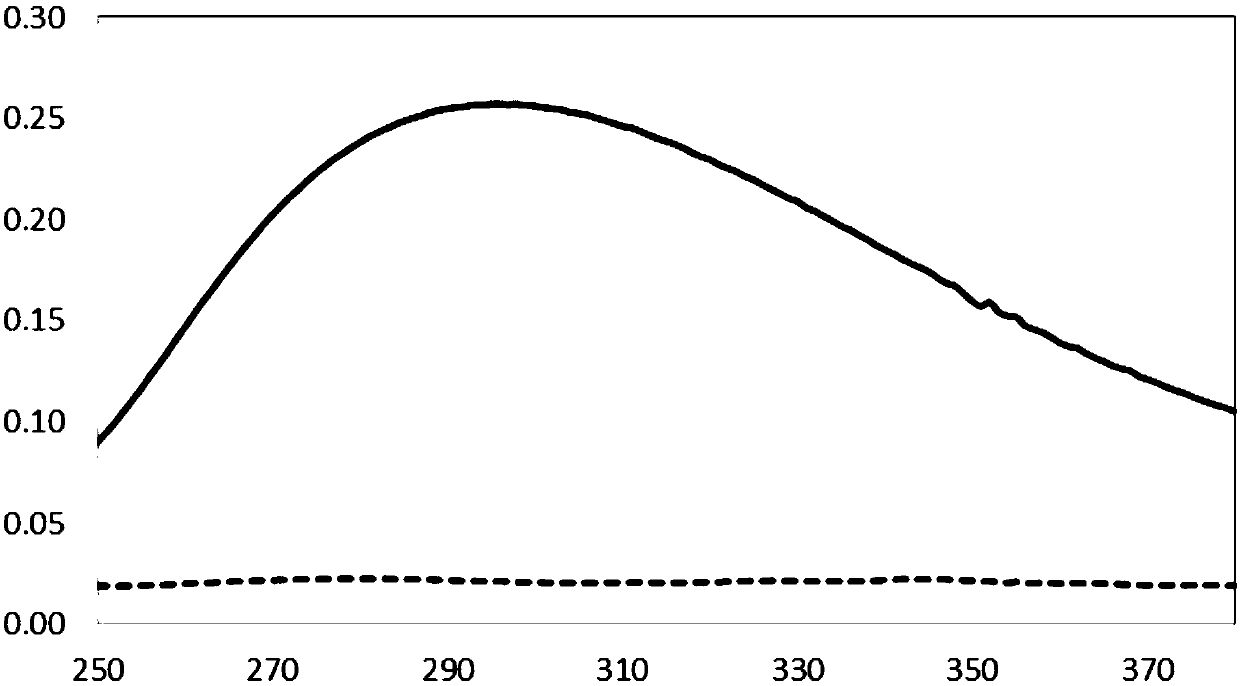
A negative photoresist material comprises, by weight percent, 6% to 10% of resin, 2% to 7% of polyfunctional monomer, 5% to 12% of pigment dispersion, 70% to 80% of a solvent, 0.1% to 0.2% of an additive, and 0.4% to 0.8% of a photoinitiator, wherein the photoinitiator has a main absorption peak at a wavelength of 300 to 330 nm in an ultraviolet absorption spectrum. The negative photoresist material provided by the invention can effectively improve the problem of a high horn angle and avoid the occurrence of light leakage when applied to the color resistance of the color filter.

Description

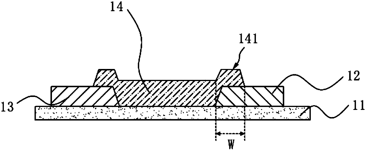
technical field [0001] The invention relates to the field of display technology, in particular to a negative photoresist material and a color filter. Background technique [0002] In the manufacturing process of TFT-LCD (thin film transistor-liquid crystal display, thin film transistor array-liquid crystal display) color filter, in order to avoid light leakage, between the red, green and blue resistors and between the red, green and blue resistors There is usually a certain overlap (Overlap) between the black matrix, and the position of the overlap cannot be completely flat, so there will be a certain height of horns. Such as figure 1 As shown, the color filter includes a base substrate 11, a red color resistance 13, a green color resistance 12, and a blue color resistance 14. , A horn 141 is formed at the overlapping joint. If the horn 141 is too high, the uneven terrain will affect the inversion of the liquid crystal after the box is formed, resulting in light leakage in...

Claims


Application Information

Patent Timeline
Patent Type & Authority Applications(China)
IPC IPC(8): G03F7/038G03F7/027G03F7/004G02B5/20
CPCG02B5/20G03F7/004G03F7/027G03F7/038
Inventor 饶夙缔
Owner TCL CHINA STAR OPTOELECTRONICS TECH CO LTD
Learn More