
A mode-locked pulsed fiber laser based on sms structure

A fiber laser, mode-locked pulse technology, applied in lasers, laser parts, phonon exciters, etc., can solve the problems of material mode-locked low damage threshold, complex structure, etc., to achieve a wide range of applications, high damage threshold, simple structure Effect

Active Publication Date: 2019-10-11
CHANGCHUN UNIV OF SCI & TECH
View PDF5 Cites 0 Cited by
  • Summary
  • Abstract
  • Description
  • Claims
  • Application Information

AI Technical Summary

Problems solved by technology

[0003] Commonly used passive mode-locking includes material mode-locking and structural mode-locking. Material mode-locking: prepare a material with nonlinear saturable absorption effect, put it into the laser, and use the nonlinear properties of this material to achieve mode-locked pulse output , this material mode-locking method needs to prepare materials, and the saturable absorber material will be damaged when the laser power is high, the material mode-locking has a lower damage threshold; structural mode-locking: common structural mode-locking has 8 Cavity mode-locking and nonlinear polarization rotation mode-locking (NPR), structural mode-locking uses a polarization controller to control the polarization state of light in the cavity, and the use of polarization-dependent isolators and other devices works together to achieve a saturable absorption effect. The traditional mode-locked structure requires the use of other devices and complex structures

Method used


Image

  • A mode-locked pulsed fiber laser based on sms structure
  • A mode-locked pulsed fiber laser based on sms structure
  • A mode-locked pulsed fiber laser based on sms structure

Examples


Embodiment Construction

[0024] In order to make the purpose, technical solutions and advantages of the embodiments of the present invention clearer, the technical solutions in the embodiments of the present invention will be clearly and completely described below in conjunction with the accompanying drawings in the embodiments of the present invention. Obviously, the described embodiments It is some embodiments of the present invention, but not all of them. Based on the implementation manners in the present invention, all other implementation manners obtained by persons of ordinary skill in the art without creative efforts fall within the protection scope of the present invention. Accordingly, the following detailed description of the embodiments of the invention provided in the accompanying drawings is not intended to limit the scope of the claimed invention, but merely represents selected embodiments of the invention. Based on the implementation manners in the present invention, all other implement...


PUM


Abstract

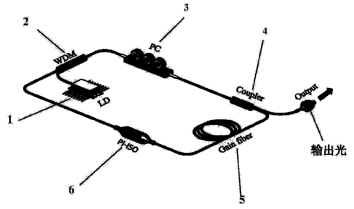
The invention relates to a mode locking pulse optical fiber laser based on an SMS structure. The mode locking pulse optical fiber laser comprises a pumping source, a wavelength division multiplexer, apolarization single-mode-multimode-single-mode structure, an output coupler, a gain optical fiber and a polarization independent isolator, wherein the pumping source is connected with the wavelengthdivision multiplexer; the wavelength division multiplexer is connected with the polarization single-mode-multimode-single-mode structure; the polarization single-mode-multimode-single-mode structure is connected with the output coupler; the output coupler is connected with the gain optical fiber; the gain optical fiber is connected with the polarization independent isolator; the polarization independent isolator is connected with the wavelength division multiplexer; and the wavelength division multiplexer, the polarization single-mode-multimode-single-mode structure, the output coupler, the gain optical fiber and the polarization independent isolator are sequentially connected to form an optical fiber ring cavity structure. The mode locking pulse optical fiber laser achieves full optical fiber mode locking in a SMS structure and polarization controller combined manner; manufacturing of a mode locking structure and a mode locking device is simplified; and compared with the traditional mode locking optical fiber laser, the mode locking pulse optical fiber laser is simpler and more compact in structure and higher in damage threshold.

Description

technical field [0001] The invention relates to a mode-locked fiber laser, in particular to a mode-locked pulsed fiber laser based on an SMS structure. Background technique [0002] Compared with traditional solid-state lasers, fiber lasers have the characteristics of simple structure, compactness and portability. There are two types of fiber laser excitation ultrashort pulses: active mode-locking and passive mode-locking. Passive mode-locking is easier to obtain ultrashort pulses than active mode-locking. [0003] Commonly used passive mode-locking includes material mode-locking and structural mode-locking. Material mode-locking: prepare a material with nonlinear saturable absorption effect, put it into the laser, and use the nonlinear properties of this material to achieve mode-locked pulse output , this material mode-locking method needs to prepare materials, and the saturable absorber material will be damaged when the laser power is high, the material mode-locking has a...

Claims


Application Information

Patent Timeline
Patent Type & Authority Patents(China)
IPC IPC(8): H01S3/098H01S3/067G02B6/255
Inventor 金亮张宏伟张贺徐英添陈华龙王铁斌潘伟马晓辉
Owner CHANGCHUN UNIV OF SCI & TECH
Learn More