Defoaming system used before density measurement of gypsum slurry

A technology of density measurement and gypsum slurry, which is applied in the direction of foam dispersion/prevention, can solve problems such as inapplicability, value jump, influence on normal operation of desulfurization system and absorption tower system, etc., and achieve the effect of easy measurement and reduction of air bubbles

Pending Publication Date: 2019-04-16
BEIJING GUODIAN LONGYUAN ENVIRONMENTAL ENG
View PDF0 Cites 1 Cited by
  • Summary
  • Abstract
  • Description
  • Claims
  • Application Information

AI Technical Summary

Problems solved by technology

[0003] When the oxidation reaction in the third step occurs, excessive oxidizing air needs to be blown in; when measuring the density of the gypsum slurry in the absorption tower, the gypsum slurry is generally introduced from the body of the absorption tower, and a large number of bubbles are also discharged with the flow of the slurry. Tiny air bubbles adhere to the gypsum crystals in the slurry, which greatly interferes with the accurate measurement of the density by the density meter, resulting in inaccurate measurement of the online density meter, large errors, and some even jumps in the value, which is harmful to desulfurization. The normal operation of the system and the absorption tower system has a great influence
[0004] The density measurement of gypsum slurry generally adopts mass flowmeter or tuning fork density meter. Both measurement methods are not suitable for the current application where there are a lot of air bubbles, similar to gas-liquid two-phase. To solve the problem of density measurement, it is necessary to focus on reducing the gas content of the slurry, restore the original characteristics of the gypsum slurry, and create favorable conditions for accurate measurement by installing a device to eliminate air bubbles

Method used


Image

  • Defoaming system used before density measurement of gypsum slurry

Examples


Embodiment Construction

[0027] The present invention will be described in further detail below in conjunction with the embodiments and accompanying drawings. It should be understood that the specific embodiments described here are only used to explain the present invention, not to limit the present invention.

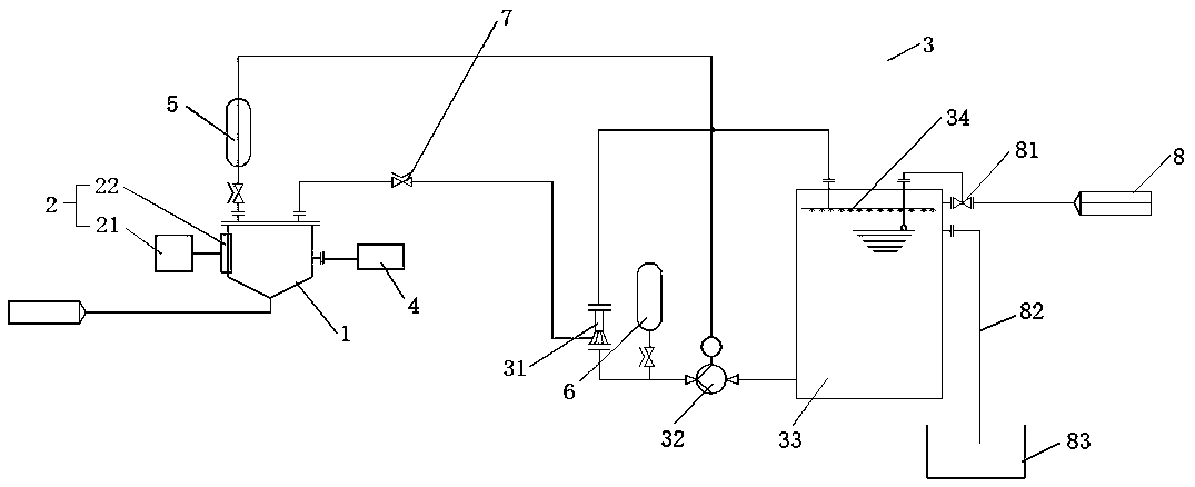
[0028] Such as figure 1 As shown, the defoaming system before measuring the density of gypsum slurry includes a defoaming box 1, an ultrasonic vibrating device 2 and a water ejector negative pressure system 3; the defoaming box 1 is a conical bottom container, and the ultrasonic vibrating device 2 is installed On the side walls around the defoaming box 1; the bottom of the defoaming box 1 is provided with a gypsum slurry inlet, the top is connected to the water ejector negative pressure system 3, and the upper part of the side wall is provided for discharging the gypsum slurry to The outlet of the density measuring device 4. The ultrasonic vibration device is used in conjunction with the wat...


PUM


Abstract

The invention discloses a defoaming system used before density measurement of gypsum slurry and belongs to the field of limestone-gypsum method desulfuration for coal-fired units of thermal power stations. The system comprises a defoaming box, an ultrasonic vibration device and a water injector negative pressure pumping system; the ultrasonic vibration device is installed on the side wall of the periphery of the defoaming box; a gypsum slurry inlet is formed in the bottom of the defoaming box, the top of the defoaming box is connected with the water injector negative pressure pumping system, and a slurry discharging port which is used for discharging the gypsum slurry to a density measurement device is formed in the upper portion of the side wall. The defoaming system has the advantages that by adopting cooperation of the ultrasonic vibration device and the water injector negative pressure pumping system, bubbles in the gypsum slurry which flows from the bottom of the defoaming box gradually upwards move under the effect of the ultrasonic vibration device, the volume of the bubbles is gradually increased, the bubbles float out of the water surface and are broken, efficient defoaming is achieved, the aim of reducing air bubbles in the liquid is achieved, and convenience is provided for liquid density measurement in the later period.

Description

technical field [0001] The invention relates to the field of limestone-gypsum desulfurization of coal-fired units in thermal power plants, in particular to a defoaming system before measuring the density of gypsum slurry. Background technique [0002] At present, the principle of limestone-gypsum desulfurization technology for coal-fired units in thermal power plants is that SO in flue gas 2 Chemically react with limestone, oxidize and crystallize to form gypsum, including SO 2 There are 4 steps of absorption, reaction with limestone, oxidation reaction and crystallization reaction. [0003] When the oxidation reaction in the third step occurs, excessive oxidizing air needs to be blown in; when measuring the density of the gypsum slurry in the absorption tower, the gypsum slurry is generally introduced from the body of the absorption tower, and a large number of bubbles are also discharged with the flow of the slurry. Tiny air bubbles adhere to the gypsum crystals in the s...

Claims


Application Information

Patent Timeline
Patent Type & Authority Applications(China)
IPC IPC(8): B01D19/02
CPCB01D19/0078B01D19/02
Inventor 金鑫彭光军
Owner BEIJING GUODIAN LONGYUAN ENVIRONMENTAL ENG
Why Eureka
Try Eureka