

Wastewater treatment device
A sewage treatment device and filter device technology, applied in the direction of filtration separation, separation methods, chemical instruments and methods, etc., can solve the problems of unable to filter residual impurities in pipelines, unable to handle impurities, etc., to achieve guaranteed reuse rate, strong practicability, well-structured effects
- Summary
- Abstract
- Description
- Claims
- Application Information
AI Technical Summary
Problems solved by technology
Method used
Image

Examples
Embodiment 1
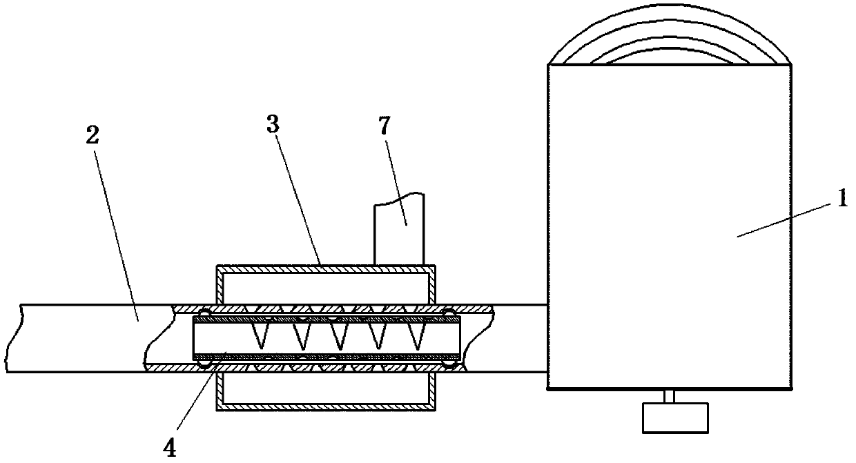
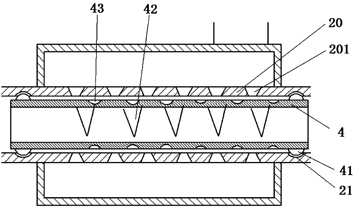
[0023] The sewage treatment device includes a filter device 1 and a pipeline 2. The pipeline 2 is installed on the liquid outlet of the filter device 1 and outputs the filtered liquid. The end of the pipeline 2 close to the filter device 1 is defined as the liquid inlet. The end of the pipeline 2 An outer pipe 3 is sleeved at the liquid inlet, and both ends of the outer pipe 3 are welded outside the pipe band 2. A cavity with a circular cross-section is formed between the outer pipe 3 and the pipe 2. The outer pipe 3 and the filter device The distance between the liquid outlets of 1 is 45 mm, the outer pipe 3 is connected with a water pipe 7, the water pipe 7 is tangent to the wall surface of the outer pipe 3, and the pipe 2 located inside the outer pipe 3 is defined as a dredging pipe 20 , the wall surface of dredging pipeline 20 is provided with small hole 201, and small hole 201 has a plurality of and is evenly arranged on dredging pipeline 20, and the diameter of small hole...
Embodiment 2
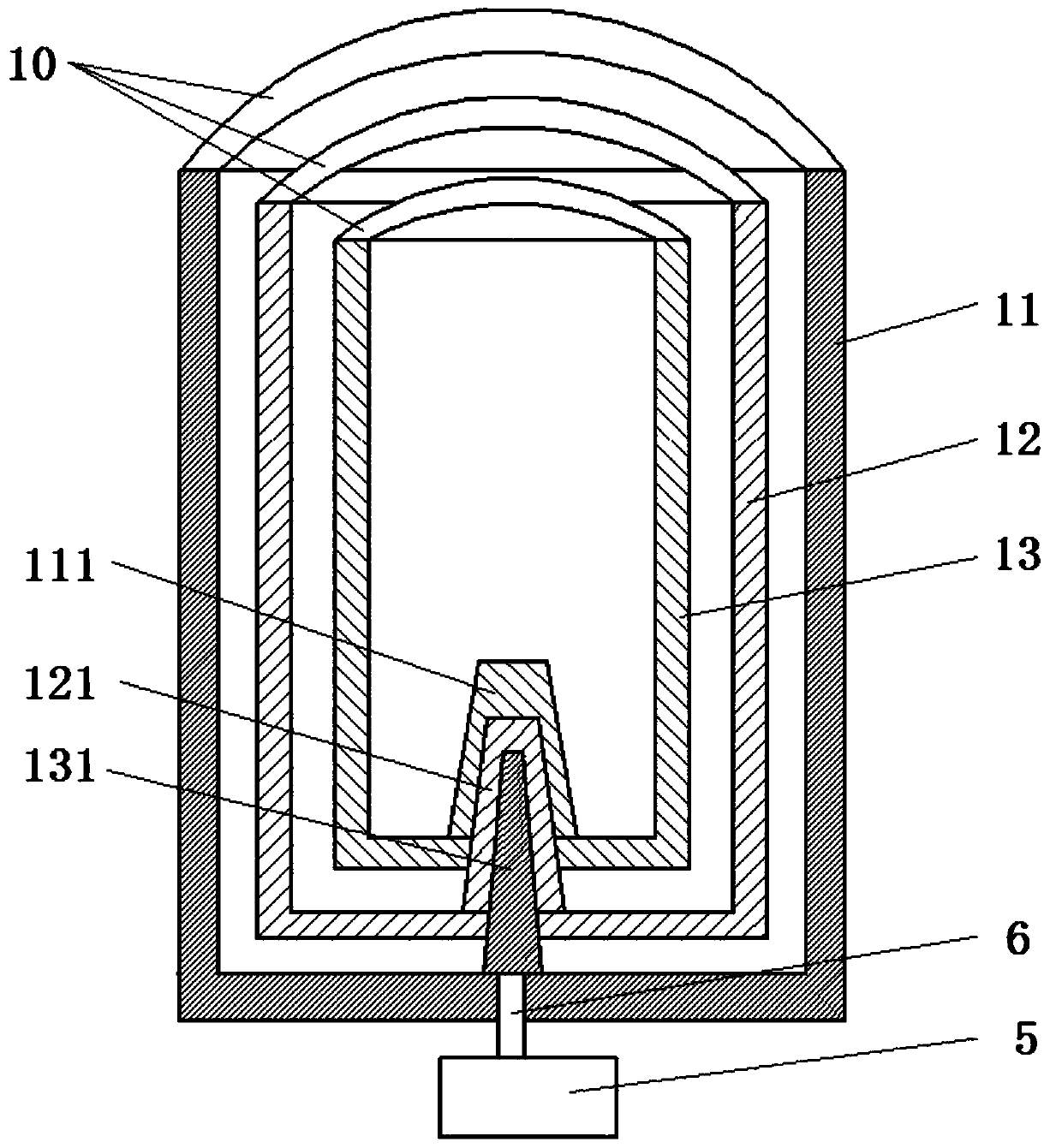
[0030] Same as embodiment 1, the difference is that the filter device 1 includes a first filter cartridge 11, a second filter cartridge 12 and a third filter cartridge 13, the upper end of the first filter cartridge 11 is opened and the sewage to be treated is input from the upper end opening, The first filter cartridge 11, the second filter cartridge 12 and the third filter cartridge 13 are nested with each other in turn, the first filter cartridge 11, the second filter cartridge 12 and the third filter cartridge 13 are provided with filter holes, the first filter cartridge 11 The diameters of the filter holes on the upper filter cartridge, the filter holes on the second filter cartridge 12 and the filter holes on the third filter cartridge 13 gradually decrease.
[0031] The bottom of the first filter cartridge 11 is provided with an upwardly protruding first shaft sleeve 111, the bottom of the second filter cartridge 12 is provided with an upwardly protruding second shaft sl...
Embodiment 3
[0034] It is the same as Embodiment 1, except that the handle 10 is installed on the first filter cartridge 11 , the second filter cartridge 12 and the third filter cartridge 13 .
PUM
 Abstract
Description
Claims
Application Information