Eureka AIR delivers breakthrough ideas for toughest innovation challenges, trusted by R&D personnel around the world.

Pushing system and method for PLC multipoint synchronous three-dimensional hydraulic bridge

A jacking and hydraulic technology, used in bridges, bridge construction, erection/assembly of bridges, etc., can solve the problems of insufficient synchronization accuracy, difficult to control the jacking and closing accuracy, and difficult to grasp the numerical accuracy of the force.

Active Publication Date: 2019-04-16
CHINA RAILWAY FIRST GRP CO LTD +1
View PDF8 Cites 8 Cited by
  • Summary
  • Abstract
  • Description
  • Claims
  • Application Information

AI Technical Summary

Problems solved by technology

However, the multi-point jacking method and the corresponding jacking system currently used have the following defects and deficiencies to varying degrees: First, the synchronization accuracy of the existing jacking equipment is not enough, and there are inevitably multiple jacking machines in the jacking process The action error of the equipment; second, the existing jacking construction method and jacking system are difficult to control the closing accuracy of the jacking under large slopes and linear complex situations; third, without fully automatic digital control, it is difficult to grasp the accuracy of the force value ; Fourth, more operators are required, labor input is large, labor-intensive and time-consuming, and construction efficiency is low; Fifth, part of the multi-point push construction also needs to use guide beams for traction, the construction investment is large, and the construction process is complicated

Method used


Image

  • Pushing system and method for PLC multipoint synchronous three-dimensional hydraulic bridge
  • Pushing system and method for PLC multipoint synchronous three-dimensional hydraulic bridge
  • Pushing system and method for PLC multipoint synchronous three-dimensional hydraulic bridge

Examples


Embodiment Construction

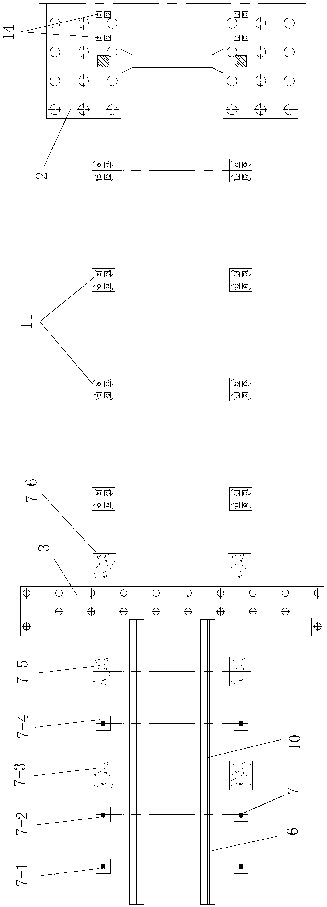
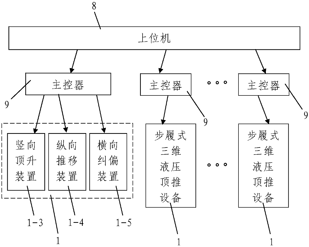
[0101] Such as figure 1 , figure 2 A PLC multi-point synchronous three-dimensional hydraulic bridge jacking system shown is characterized in that it includes a jacking monitoring system and multiple sets of walking-type three-dimensional hydraulic jacking equipment 1 for pushing the steel box girder to be pushed, and multiple sets The walking three-dimensional hydraulic pushing equipment 1 is laid out from front to back along the length direction of the pushed steel box girder; A steel box girder spliced ​​from front to back by a plurality of steel box girder segments 4, the mid-span pier 2 and beam end pier 3 are permanent pier arranged vertically and both are steel bars Concrete pier, the front end of the pushed steel box girder is supported on the mid-span pier 2 and its rear end is supported on the beam end pier 3; The length direction of the pushing steel box girder is provided with a plurality of temporary buttresses 11 supporting the pushed steel box girder from the ...


PUM


Abstract

The invention discloses a pushing system and method for a PLC multipoint synchronous three-dimensional hydraulic bridge. The pushing system comprises a pushing monitoring system and multiple groups ofwalking-type three-dimensional hydraulic pushing devices for pushing pushed steel box beams, and each pushing buttress is provided with a left temporary supporting base and a right temporary supporting base which are symmetrically distributed. The pushing method includes the steps of 1, constructing assembly jig frames and temporary buttresses; 2, constructing a three-dimensional adjusting device, the pushing devices and the temporary supporting bases; 3, carrying out steel-box-beam assembling and synchronous pushing; 4, carrying out steel-box-beam pushing. According to the pushing system andmethod for the PLC multipoint synchronous three-dimensional hydraulic bridge, steel box beams are synchronously pushed forwards multiple times through the multiple groups of walking-type three-dimensional hydraulic pushing devices, pushing controlling is easy and convenient, synchronous action of the multiple groups of walking-type three-dimensional hydraulic pushing devices can be easily and conveniently achieved, pushing positions are flexibly distributed, guide beams and sliding rail beams for longitudinal pushing are not required, self-balancing pushing is really achieved, and the pushingprocess is safe and reliable.

Description

technical field [0001] The invention belongs to the technical field of bridge construction, and in particular relates to a PLC multi-point synchronous three-dimensional hydraulic bridge jacking system and a jacking method. Background technique [0002] With the continuous improvement of my country's bridge design and construction technology, a large number of continuous steel box girder bridges have emerged in the fields of highways, urban transportation, and railways. The jacking method is widely used in its construction due to the advantages of less land occupation, no impact on the traffic under the bridge, no need for large lifting equipment, safety and reliability, and low cost. The jacking method construction is to set up a prefabricated field behind the abutment along the bridge axis direction, and set up steel guide beams, temporary piers, slideways, horizontal jacks (also called jacking force devices or jacking force devices), etc., the actual During construction, ...

Claims


Application Information

Patent Timeline
IPC IPC(8): E01D21/00
CPCE01D21/00
Inventor 陈宏俊汪惺冯敬辉杜亮苏金阳贺振华高良罗彭韦凡郝洪波齐浩东
Owner CHINA RAILWAY FIRST GRP CO LTD
Why Eureka
Eureka Blog
Learn More