
Horizontal directional drilling machine for clamping and turning and using method thereof

A technology of horizontal directional drilling rig and clamping seat, which is applied in directional drilling, drilling equipment and methods, drilling equipment, etc., and can solve the problem of general fixation, low installation efficiency of drill pipes, and unguaranteed drilling quality of drill pipes, etc. problems, to achieve the effect of improving placement stability, improving installation efficiency, and ensuring drilling quality

Inactive Publication Date: 2019-04-16
湖南润成机械有限公司
View PDF6 Cites 5 Cited by
  • Summary
  • Abstract
  • Description
  • Claims
  • Application Information

AI Technical Summary

Problems solved by technology

Existing horizontal directional drilling rigs lack photovoltaic power generation devices, so that the drilling rig consumes a large amount of external power resources. At the same time, the fixity of the backing plate of the existing horizontal directional drilling rig is general, making the backing plate unstable, which in turn makes the drilling of the drill pipe difficult. The hole quality cannot be guaranteed, and the existing horizontal directional drilling machine is mostly operated manually when installing the drill pipe, which makes the installation efficiency of the drill pipe low, so there is an urgent need for a horizontal directional drilling machine for clamping and turning something wrong

Method used


Image

  • Horizontal directional drilling machine for clamping and turning and using method thereof
  • Horizontal directional drilling machine for clamping and turning and using method thereof
  • Horizontal directional drilling machine for clamping and turning and using method thereof

Examples


Embodiment Construction

[0024] The present invention will be further described below in conjunction with accompanying drawing:

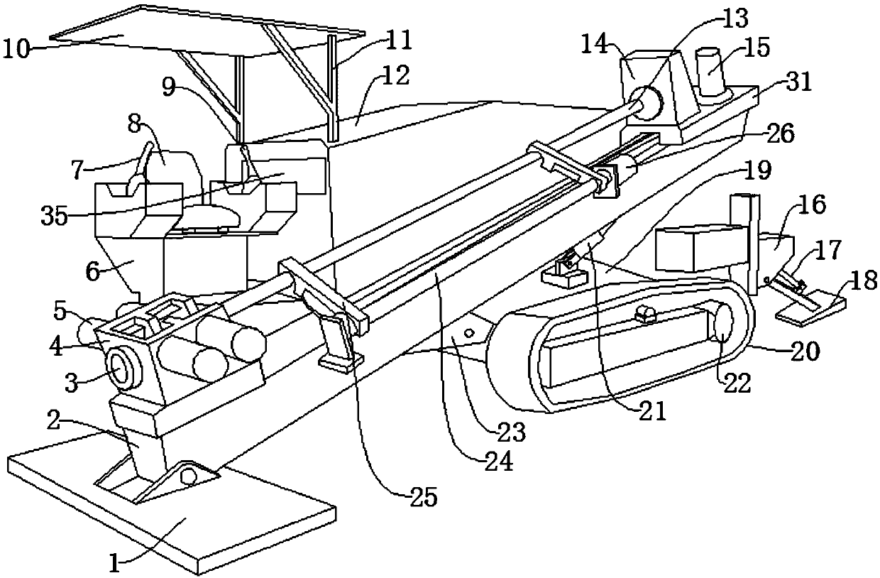
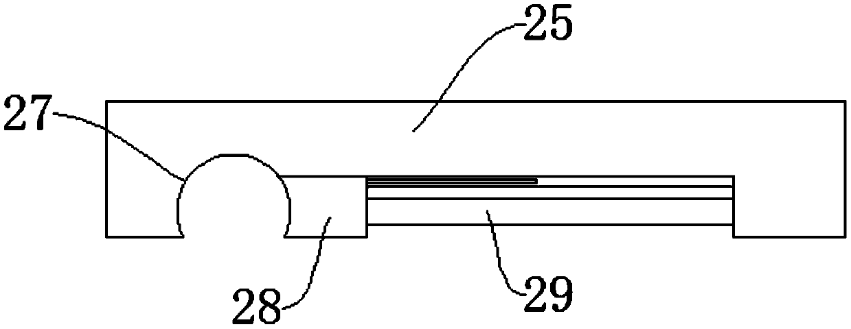
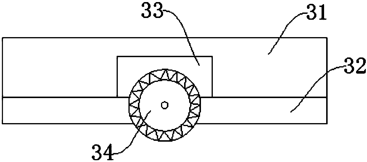
[0025] like Figure 1-Figure 4 As shown, a horizontal directional drilling machine for clamping and turning includes a backing plate 1, a cross bar 2 and a clamping seat 4, the top side of the backing plate 1 is provided with the cross bar 2, and the cross bar 2 is The clamping seat 4 is provided on the side, and the lower side of the backing plate 1 is provided with fixed teeth 30, the fixed teeth 30 can ensure the stability of the backing plate 1, and the side wall of the clamping seat 4 is provided with a fixed Hole 3, clamping hydraulic cylinder 5 is provided on the outside of the clamping seat 4, a lever seat 25 is provided on one side of the cross bar 2, and a rotating rod 24 is provided on one side of the rod seat 25, and the rotating rod 24 can drive the rod seat 25 to rotate, the rod seat 25 is provided with a rod groove 27, a sliding block 28 is arranged on one s...


PUM


Abstract

The invention discloses a horizontal directional drilling machine for clamping and turning and a using method thereof. The horizontal directional drilling machine for clamping and turning comprises abacking plate, a cross bar and a clamping seat, wherein the upper side of a bottom plate is provided with the cross bar, the upper side of the cross bar is provided with the clamping seat, the lower side of the backing plate is provided with fixing teeth, and a fixing hole is formed in one side wall of the clamping seat. The horizontal directional drilling machine has the advantages that the machine can execute photoelectric conversion and thus convert solar energy into electric energy and provide electric energy through an arranged solar panel, the consumption of external power resources is reduced; by means of the arranged fixing teeth, the placement stability of the backing plate is greatly improved, and thus the drilling quality of a drill rod is ensured; by means of a second rotary hydraulic cylinder, a rotating rod, a clamping rod seat, a rod groove, a sliding block and a third hydraulic rod which are arranged, installation of the drill rod is mechanically and automatically executed, and the installation efficiency of the drill rod is improved.

Description

technical field [0001] The invention relates to the field of horizontal directional drilling machines, in particular to a horizontal directional drilling machine for clamping and flipping and a use method thereof. Background technique [0002] Horizontal directional drilling rig is a kind of construction machinery for laying various underground public facilities without excavating the ground surface. Sand, clay, pebbles and other ground conditions can be constructed in most non-hard rock areas in my country, and the working environment temperature is -15℃~+45℃. Existing horizontal directional drilling rigs lack photovoltaic power generation devices, so that the drilling rig consumes a large amount of external power resources. At the same time, the fixity of the backing plate of the existing horizontal directional drilling rig is general, making the backing plate unstable, which in turn makes the drilling of the drill pipe difficult. The hole quality cannot be guaranteed, and...

Claims


Application Information

Patent Timeline
Patent Type & Authority Applications(China)
IPC IPC(8): E21B7/04E21B7/02E21B15/04
CPCE21B7/02E21B7/046E21B15/04
Inventor 蔡日光
Owner 湖南润成机械有限公司
Learn More