
Meshing seal structure and aircraft engine with same

An aero-engine and mouthpiece technology, applied in engine components, machines/engines, mechanical equipment, etc., can solve problems affecting aerodynamic efficiency, thermal airflow interference, etc., to achieve good sealing effect, good sealing effect, and reduce ventilation effect. Effect

Active Publication Date: 2019-04-16
AECC SHENYANG ENGINE RES INST
View PDF14 Cites 4 Cited by
  • Summary
  • Abstract
  • Description
  • Claims
  • Application Information

AI Technical Summary

Problems solved by technology

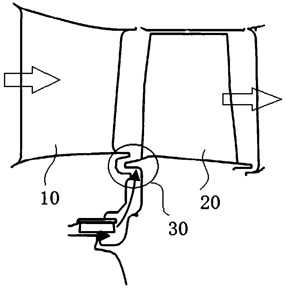
Normally, the mouthpiece sealing structure 30 is composed of an axial protruding tooth and a corresponding groove, but although this structure can prevent the inflow of airflow to a certain extent, it also makes the flow from the gap into the main channel to a certain extent The cooling gas interferes with the thermal flow in the main channel, affecting aerodynamic efficiency

Method used


Image

  • Meshing seal structure and aircraft engine with same
  • Meshing seal structure and aircraft engine with same
  • Meshing seal structure and aircraft engine with same

Examples


Embodiment Construction

[0016] In order to make the purpose, technical solution and advantages of the application more clear, the technical solution in the embodiment of the application will be described in more detail below in conjunction with the drawings in the embodiment of the application.

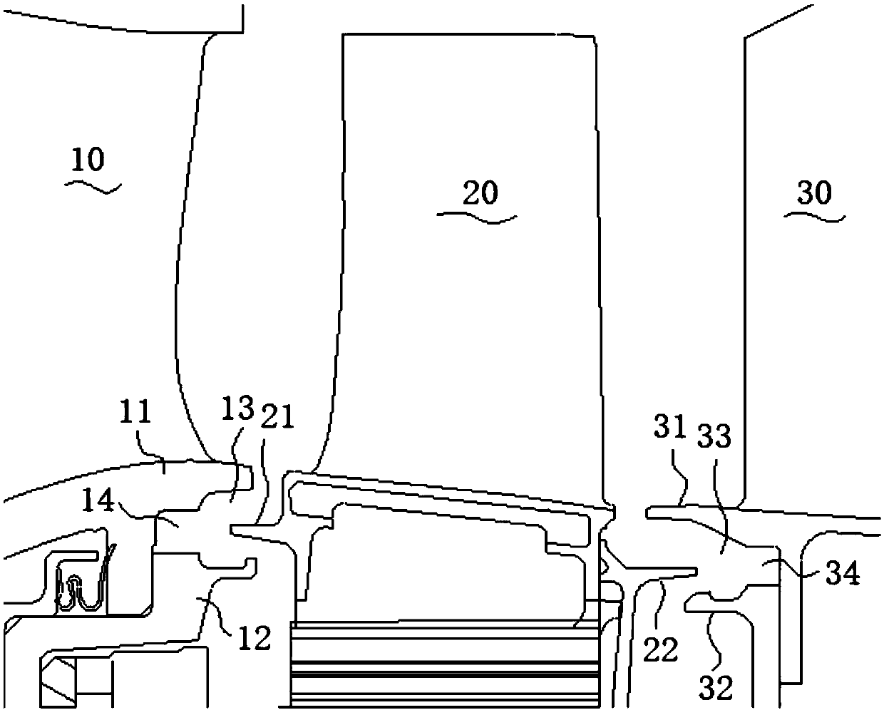
[0017] like figure 1 As shown, there is a rotor blade 20 between the two stator blades 10, 30, the root of the rotor blade 20 has a first rotating tooth 21 and a second rotating tooth 22 on both sides in the axial direction, and the root of the stator blade 10 of the previous stage has The guide vane 11 and the guide vane inner ring 12 installed together with the guide vane 11, there is a first-stage groove 13 and a second-stage groove 14 between the guide vane 11 and the guide vane inner ring 12, and the first-stage rotating teeth 21 Extending into the part of the groove 13 of the first stage, the cooling air flow flows through from bottom to top. There are guide vanes 31 and guide vane inner rings 32 inst...


PUM


Abstract

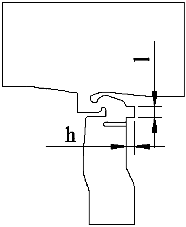
The invention discloses a meshing seal structure. The meshing seal structure comprises a rotor blade and stator blades, wherein rotating teeth protruding towards the root parts of the stator blades are arranged on the root part of the rotor blade; and first-stage grooves matched with the rotating teeth are formed in the root parts of the stator blades, second-stage grooves are further formed in the first-stage grooves, and the rotating teeth, the first-stage grooves and the second-stage grooves form a meshing seal unit. According to the meshing seal structure, the motion direction of jet flowafter throttling is changed, the breathability effect is reduced, the change of the throttling position and throttling area of a tooth tip are directly influenced by the size of the meshing seal structure, the influence on labyrinth seal performance is great, the plate edge labyrinth leakage amount is reduced due to the meshing seal structure with the grooves, and a better seal effect is achieved;groove structural parameters are designed to follow the relationship of I=+ / -1.23h by the computational analysis and experimental verification, and the obtained seal effect is better.

Description

technical field [0001] The application belongs to the technical field of aero-engines, and in particular relates to a mouthpiece sealing structure and an aero-engine having the same. Background technique [0002] The mouth seal of the aero-engine / gas-turbine engine is a structure composed of the turbine guide vane, the cavity part below the root of the working blade and the upper part of the blade. It is a non-contact seal, which is used to prevent or reduce the mainstream high temperature. Gas enters the rim cavity between the rotating and stationary discs. [0003] like figure 1 As shown, the airflow passes through the rotor blade 10 and the stator blade 20 sequentially from left to right, there is a gap between the rotor blade 10 and the stator blade 20, in order to prevent the airflow from flowing into the gap, there is a gap between the rotor blade 10 and the stator blade 20 The mouthpiece sealing structure 30 passes the cooling gas from the inside to the main channel...

Claims


Application Information

Patent Timeline
IPC IPC(8): F01D11/04F01D5/30F01D9/02
CPCF01D5/30F01D9/02F01D11/001F01D11/04
Inventor 程瑞罡陈浩王广宁
Owner AECC SHENYANG ENGINE RES INST
Learn More