
A Method for Spatial Position Registration of Synchronous Phase-shifting Interferogram of Dynamic Interferometer

A technology of synchronous phase shifting and dynamic interference, applied in the field of optical interferometry, can solve the problems of low automation and high imaging quality requirements in specific structures and specific measurement occasions, so as to reduce manual operation steps and improve automation The degree and method are simple and efficient

Active Publication Date: 2020-11-27
NANJING UNIV OF SCI & TECH
View PDF9 Cites 0 Cited by
  • Summary
  • Abstract
  • Description
  • Claims
  • Application Information

AI Technical Summary

Problems solved by technology

The artificial spatial position registration method does not require algorithmic considerations, but it has high requirements on the imaging quality of the characteristic target, and the target recognition in the sub-interferogram contains human factors, and the degree of automation is not high
[0005] In the automatic spatial position registration method, some methods rely on the gray distribution information of the image, so the reliability is affected by factors such as imaging quality, random noise, and the splitting ratio of the spectroscopic module; The position registration of the image has specific requirements for the shape of the interferogram, and the edge of the interferogram needs to be clearly imaged; some methods can only be applied to specific structures and specific measurement occasions, which makes the registration algorithm have many restrictions in actual use; some methods The amount of calculation is large, and the registration efficiency is not high

Method used


Image

  • A Method for Spatial Position Registration of Synchronous Phase-shifting Interferogram of Dynamic Interferometer
  • A Method for Spatial Position Registration of Synchronous Phase-shifting Interferogram of Dynamic Interferometer
  • A Method for Spatial Position Registration of Synchronous Phase-shifting Interferogram of Dynamic Interferometer

Examples


Embodiment 1

[0068] The spatial position registration of the synchronous phase-shifted interferogram is realized by using the dynamic Fizeau interferometer based on the spatial phase shifting of point light sources. Phase-shifted interferogram.

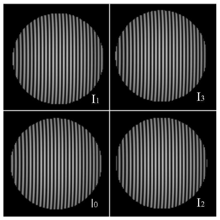
[0069] Step 1: The reference mirror in the heterogeneous dynamic Fizeau interferometer with inclined point light source introduces linear carrier frequency into four synchronous phase-shifting interferograms at the same time, collects the carrier frequency phase-shifting interferogram, and divides the carrier frequency phase-shifting interferogram Each sub-interferogram of , numbered as I 0 , I 1 , I 2 , I 3 ,Such as Figure 5 shown.

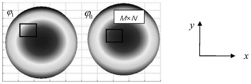
[0070] Step 2, use the Fourier filter method to solve the phase information in each sub-interferogram, and de-tilt it, and obtain the phase information to be measured contained in each sub-interferogram, which are numbered in turn as Such as Figure 5 shown;

[0071] Step 3, to sub-interferogram I 0 The co...


PUM


Abstract

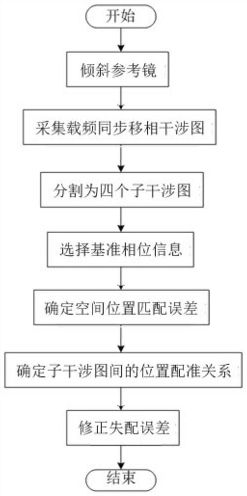
The invention discloses a space location registration method of a synchronous phase-shifted interferogram of a dynamic interferometer. The method comprises the following steps: firstly inclining a reference mirror in the dynamic interferometer, importing linear carrier frequency in the synchronous phase-shifted interferogram, collecting the carrier frequency synchronous phase-shifted interferogram, and dividing the carrier frequency synchronous phase-shifted interferogram into four sub-interferograms; solving phase information of each sub-interferogram by using Fourier filter method, and performing inclination elimination on the phase information to obtain to-be-measured phase information contained in each; and then selecting the phase information contained in one interferogram as standardphase information, determining a space location matching error of the phase information contained in other interferograms and the standard phase information by adopting a quick phase correlation registration method; and finally determining a location registration relation among the sub-interferograms according to the space location matching error of the phase information. The automation degree ofthe space location registration of the dynamic interferometer is improved, the accuracy and the reliability of the space location registration are improved, the method is simple and efficient and theapplicable range is wide.

Description

technical field [0001] The invention belongs to the technical field of optical interferometry, in particular to a spatial position registration method of a synchronous phase-shifting interferogram of a dynamic interferometer. Background technique [0002] The dynamic interferometer can suppress the influence of time-varying environmental factors on the measurement results to a large extent, and can be applied to online detection on the optical processing site. The characteristic of the dynamic interferometer is that multiple synchronous phase-shifted interferograms are acquired at the same time. When calculating the phase, if the position of the interferogram does not match, a phase error will be introduced. There are two main reasons for the position mismatch of the interferogram: 1) The multi-camera system collects the interferogram at different positions, resulting in the mismatch of the position of the interferogram; 2) The single-camera system collects a single frame i...

Claims


Application Information

Patent Timeline
Patent Type & Authority Patents(China)
IPC IPC(8): G01J9/02
CPCG01J9/02G01J2009/0238
Inventor 陈磊杨影丁煜郑东晖朱文华韩志刚郑权孔璐王冲王云涛杨光吴志飞
Owner NANJING UNIV OF SCI & TECH
Learn More