Rapid location method for pressure test failure of fracturing system

A positioning method and pressure test technology, applied in the testing of machines/structural components, instruments, measuring devices, etc., can solve the problem of high risk of equipment and personnel, achieve low probability of equipment loss, improve pressure test efficiency, and improve safety. sexual effect

Active Publication Date: 2020-11-06
中石化四机石油机械有限公司 +2
View PDF5 Cites 0 Cited by
  • Summary
  • Abstract
  • Description
  • Claims
  • Application Information

AI Technical Summary

Problems solved by technology

Under the condition of low pressure, manual control is usually used for pressure test. Under the condition of high pressure, this scheme is more dangerous to equipment and personnel, and the existing operation scheme is difficult to meet the requirements.
There is no related record in the prior art

Method used


Image

  • Rapid location method for pressure test failure of fracturing system
  • Rapid location method for pressure test failure of fracturing system
  • Rapid location method for pressure test failure of fracturing system

Examples


Embodiment 1

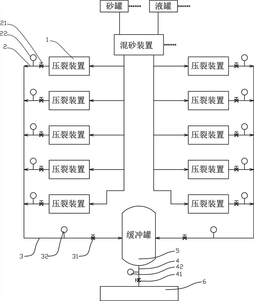
[0044] like figure 1 , 4 Among them, a method for quickly locating a pressure test fault in a fracturing system includes the following steps:

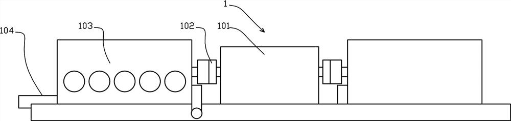
[0045] S01. The discharge pipeline 104 of each fracturing device 1 is connected to the trunk pipeline 3 through the branch pipeline 2, and the trunk pipeline 3 is connected to the bus pipeline 4. The branch pipeline 2 is provided with a branch valve 21 and a branch pressure sensor 22. A trunk valve 31 and a trunk pressure sensor 32 are provided on the trunk pipeline 3, and a bus valve 41 and a bus pressure sensor 42 are provided on the bus pipeline 4;

[0046] Close the bus valve 41, and the main controller sends a signal to make a part of the branch controllers control the output pressure of the fracturing device 1;

[0047] The bus pressure sensor 42 outputs a pressure signal, and the main controller receives the pressure signal and compares it with a preset pressure value;

[0048] S02, regrouping, the main controller gives a sig...

Embodiment 2

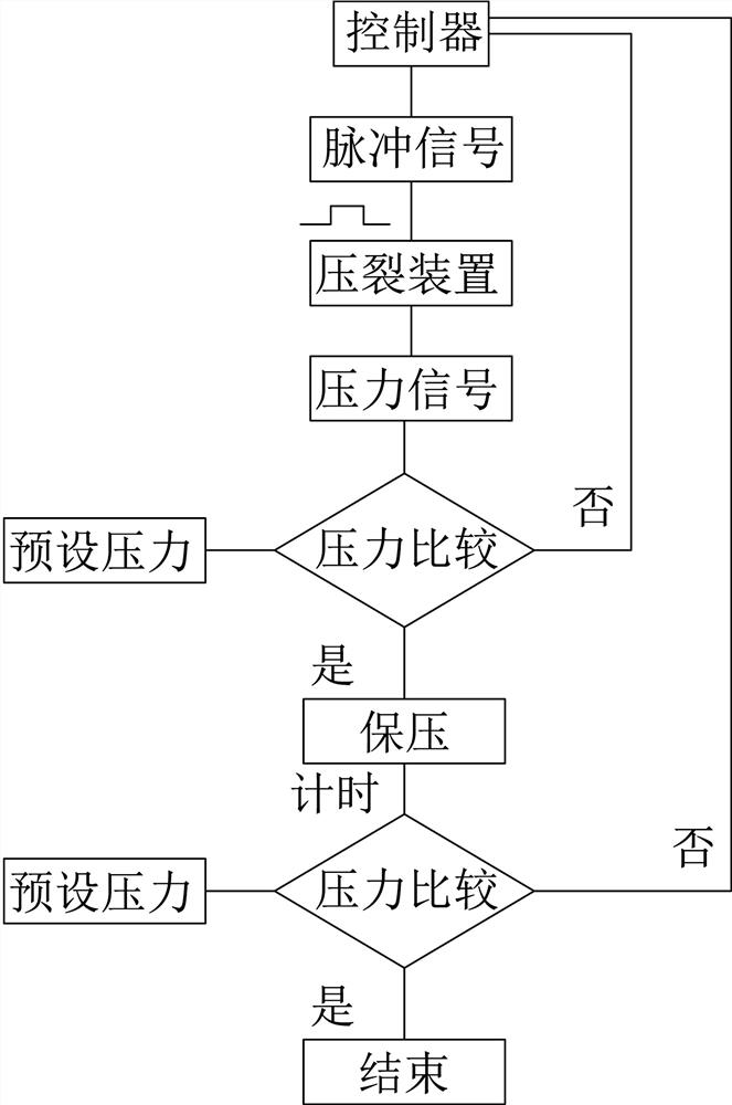
[0064] The preferred solution is as image 3 In the above, after the fault location is determined, the pressure test verification is carried out on a single fracturing device 1, and the specific steps are as follows:

[0065] S001, closing the valve of the discharge pipeline 104 of the fracturing device 1;

[0066] S002. The controller outputs a pulse signal to drive the motor of the fracturing device 1 to rotate to increase the pressure of the discharge pipeline 104, and the pressure sensor of the discharge pipeline 104 outputs a pressure signal; the pulse signal is within a preset period of time The pulse signal, the duration is 0.1~2 seconds;

[0067] The pulse signal is used as the command signal of the motor inverter, and the motor inverter controls the rotation of the motor;

[0068] S003. The controller receives the pressure signal and compares it with the preset pressure value. If it reaches the pressure, it maintains the pressure. If it does not, it outputs the same...


PUM


Abstract

The invention provides a fracturing system pressure test fault rapid positioning method. The method comprises the following steps that fracturing devices in the fracturing system are grouped for multiple times, the main controller gives out signals to enable the fracturing devices of all groups to output pressure, all the fracturing devices controlled by branch controllers participate in outputting pressure; when pressure fed back by a bus pressure sensor reaches a set value, the pressure is maintained; after a period of pressure maintaining, a current pressure signal output by the bus pressure sensor is read and compared with the preset pressure value, and if the current pressure value is within the setting range of the preset pressure value, the pressure test is completed; if the currentpressure value exceeds the setting range of the preset pressure value, a fault alarm is output, a fault positioning step is started, and fracturing system pressure test fault rapid positioning is realized. According to the method, the safety of the pressure testing operation is greatly improved, pressure testing efficiency is improved, and by adopting a scheme of grouping and calibrating a pressure increase curve, a fault point can be quickly positioned.

Description

technical field [0001] The invention relates to the field of oil drilling and production equipment, in particular to a method for quickly locating a pressure test failure of a fracturing system. Background technique [0002] Fracturing is a major measure to increase and stabilize production in the exploration and development of oil and gas fields. Multiple high-power fracturing equipment is used to form a fracturing system, such as figure 1 As shown in , the reservoir rock is fractured and diversion channels are created. With the development of ultra-deep well and horizontal well technology, the power of the required fracturing unit is increasing, and the weight and volume of a single fracturing equipment are also increasing. For example, the output pressure of the existing equipment reaches 175Mpa. Due to the high pressure, it is necessary to perform a pressure test on the equipment before each shutdown and put into use to ensure that the equipment is in good working condi...

Claims


Application Information

Patent Timeline
Patent Type & Authority Patents(China)
IPC IPC(8): G01M99/00
CPCG01M99/005
Inventor 王庆群肖勇王云海李莉莉彭平生石权刘灼范杰陆英娜徐琬
Owner 中石化四机石油机械有限公司
Why Eureka
Try Eureka