Voice coil motor powered by electromagnetic induction

A voice coil motor, electromagnetic induction technology, applied in the direction of magnetic circuit shape/style/structure, electrical components, electromechanical devices, etc., to achieve the effect of reducing dynamic electromotive force, less motion obstruction, and light weight

Active Publication Date: 2019-04-16
NANJING UNIV OF AERONAUTICS & ASTRONAUTICS
View PDF15 Cites 7 Cited by
  • Summary
  • Abstract
  • Description
  • Claims
  • Application Information

AI Technical Summary

Problems solved by technology

However, with the increasing use of voice coil motors, the limitations and disadvantages of moving coils wit...

Method used


Image

  • Voice coil motor powered by electromagnetic induction
  • Voice coil motor powered by electromagnetic induction
  • Voice coil motor powered by electromagnetic induction

Examples


Embodiment 1

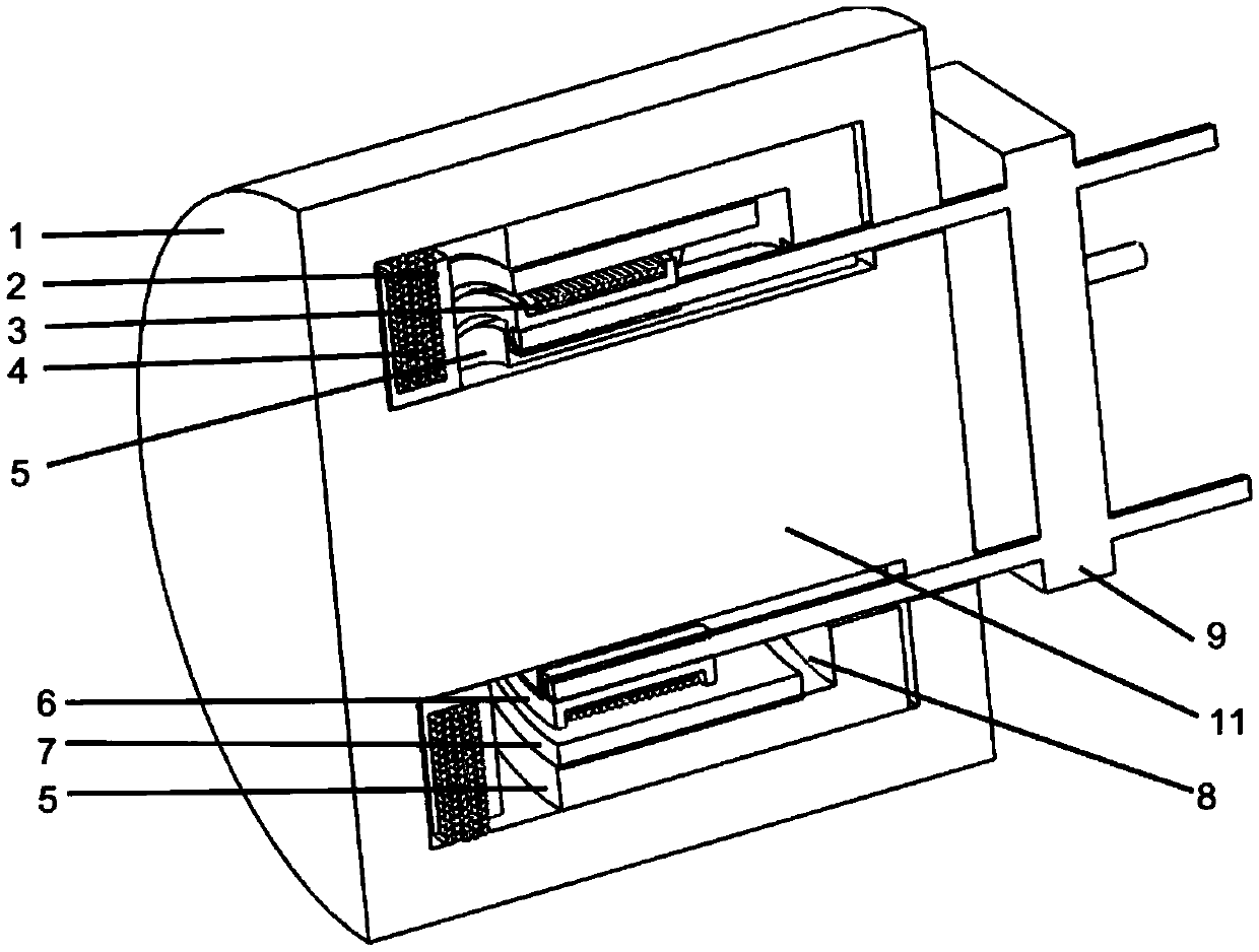
[0029] An alternative is a cylindrical voice coil motor such as figure 1 A cutaway view of a cylindrical voice coil motor is shown. The voice coil motor includes a moving coil 3, a high-frequency power supply coil 4, an annular permanent magnet 7, an annular magnetizer 5 and a magnetic core. The magnetic core is composed of a cylindrical magnetic core shell 1 and a cylindrical magnetic core column 11, the central axes of which coincide and the two ends are connected. The high-frequency power supply coil 4 and the moving coil 3 are coupled through the cylindrical magnetic core column 11, and a high-frequency excitation current is applied to the high-frequency power supply coil, and an induced current will be generated in the moving coil, thereby extending the magnetic core column under the action of the ampere force axial movement.

[0030] The annular magnetizer 5 is made of laminated silicon steel sheets, and an annular groove 8 is arranged on it, and the cylindrical magnet...

Embodiment 2

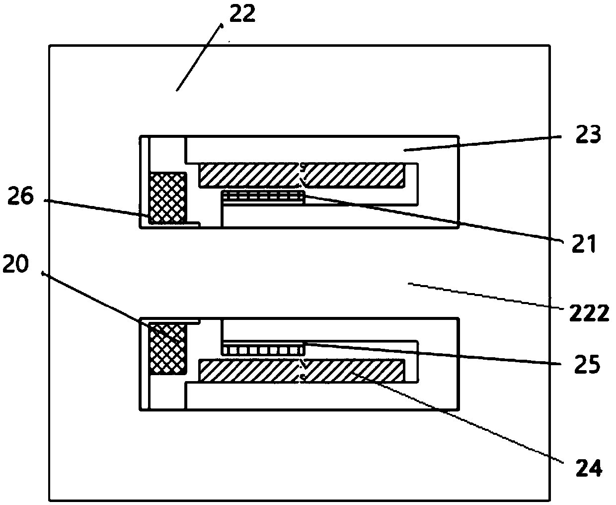
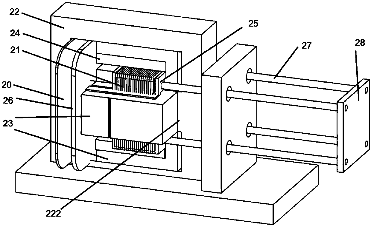
[0034] Another option is a rectangular voice coil motor, figure 2 and image 3 They are the sectional view and the complete perspective view of the main body of the motor respectively. It can be seen from the sectional view that the motor includes a moving coil 21 , a high-frequency power supply coil 20 , a bar-shaped permanent magnet 24 , a U-shaped magnetic conductor 23 and at least one set of EE-shaped magnetic cores 22 . The EE-type magnetic core 22 is composed of an EE shell and a core center column 222 , wherein the core center column 222 can be circular or square.

[0035]The U-shaped magnetic conductor 23 is made of laminated silicon steel sheets, and is arranged in the window of the EE-shaped magnetic core 22 . One side of the U-shaped magnetic conductor 23 is attached to the high-frequency magnetic core center column 222, and is driven by a 21-turn chain. The other side of the U-shaped magnetic conductor 23 is attached to the permanent magnet, and the outer surfac...


PUM


Abstract

The invention discloses a voice coil motor powered by electromagnetic induction, which comprises a moving coil, a low-frequency magnetic circuit component and a high-frequency induction power supply component. The high-frequency induction power supply component comprises a high-frequency magnetic core and a high-frequency power supply coil. The moving coil is coupled to the high-frequency power supply coil through the high-frequency magnetic core, and is used for generating an induction current in the moving coil. The low-frequency magnetic circuit component is used for providing a low-frequency magnetic field, and includes a permanent magnet and a magnetizer with a groove. The permanent magnet is attached to one side of the inner wall of the groove. An air gap is formed between the permanent magnet and the other side of the inner wall of the groove. The moving coil moves in the air gap. The flying wire of the mover coil of the voice coil motor is removed, the problem that the flying wire structure of the traditional moving coil is easy to break is solved, the reliability of the voice coil motor is improved, and the service life of the voice coil motor in the occasion of frequent reciprocating motion is greatly increased. Meanwhile, the reciprocating frequency of the voice coil motor with stroke above millimeter level is also improved.

Description

technical field [0001] The invention relates to a voice coil motor, in particular to a voice coil motor with a moving coil without a flexible power supply line structure. Background technique [0002] Voice Coil Motor (Voice Coil Motor, VCM) is a special form of direct drive motor, named because its principle is similar to that of a speaker. It is a transmission device that directly converts electrical energy into linear or arc motion mechanical energy. The voice coil motor has the advantages of simple structure, small size, low noise, high specific thrust, high acceleration, fast response, high precision, convenient maintenance, high reliability, and wide speed range. It is widely used in precision positioning systems such as hard disk drives, optical disc drives, scanners, lens focusing, laser cutting, piston lathe tool holders, mobile phones (as vibration motors), medical devices and aerospace instruments (such as aerospace refrigerators). With the development and improv...

Claims


Application Information

Patent Timeline
IPC IPC(8): H02K33/02H02K1/34H02K41/035
CPCH02K1/34H02K33/02H02K41/0356
Inventor 黄维康曹力黄文新陈乾宏
Owner NANJING UNIV OF AERONAUTICS & ASTRONAUTICS
Why Eureka
Try Eureka