
Adaptive broadband phase-locked loop circuit

An adaptive, phase-locked loop technology, applied in the direction of electrical components, automatic power control, etc., can solve the problems of inability to suppress noise interference, large phase-locked loop deviation, long acquisition time, etc., to achieve adaptive bandwidth adjustment, Meet the requirements of the clock and the effect of optimal performance parameters

Pending Publication Date: 2019-04-16
BEIJING MXTRONICS CORP +1
View PDF8 Cites 7 Cited by
  • Summary
  • Abstract
  • Description
  • Claims
  • Application Information

AI Technical Summary

Problems solved by technology

[0005] Fixed bandwidth PLLs have drawbacks, such as choosing a lower bandwidth, which will result in longer acquisition time or larger chip area; when the PLL operating conditions change, the fixed bandwidth value makes the PLL unable to suppress more Noise interference; fixed PLL parameters are easily affected by process, power supply voltage and temperature changes, making the final parameters of the PLL deviate from the design value; in addition, the fixed bandwidth PLL has high circuit cost

Method used


Image

  • Adaptive broadband phase-locked loop circuit
  • Adaptive broadband phase-locked loop circuit
  • Adaptive broadband phase-locked loop circuit

Examples


Embodiment Construction

[0047] The present invention will be described in detail below in conjunction with the accompanying drawings and specific embodiments.

[0048] The invention provides a specific embodiment of an adaptive broadband phase-locked loop circuit. The circuit includes a frequency divider 101, a frequency-to-phase detector 102, an adaptive driver 103, a first voltage-to-current converter 104, a charge pump 105, a loop filter 108, a second voltage-to-current converter 106 and a ring oscillator Controller module 107. in:

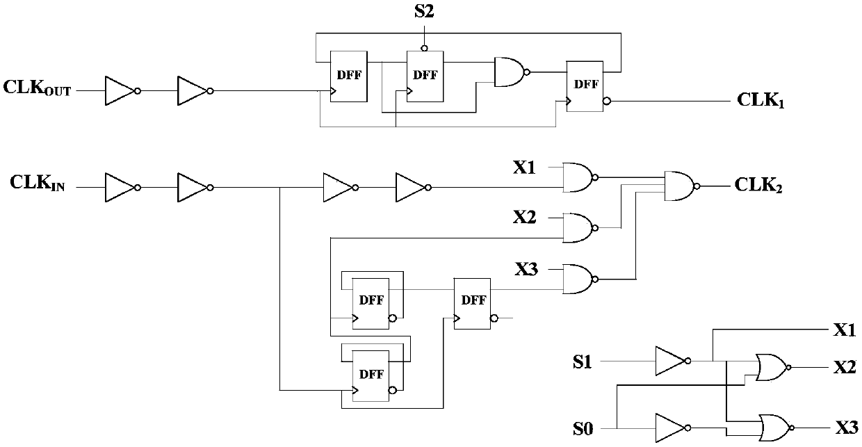
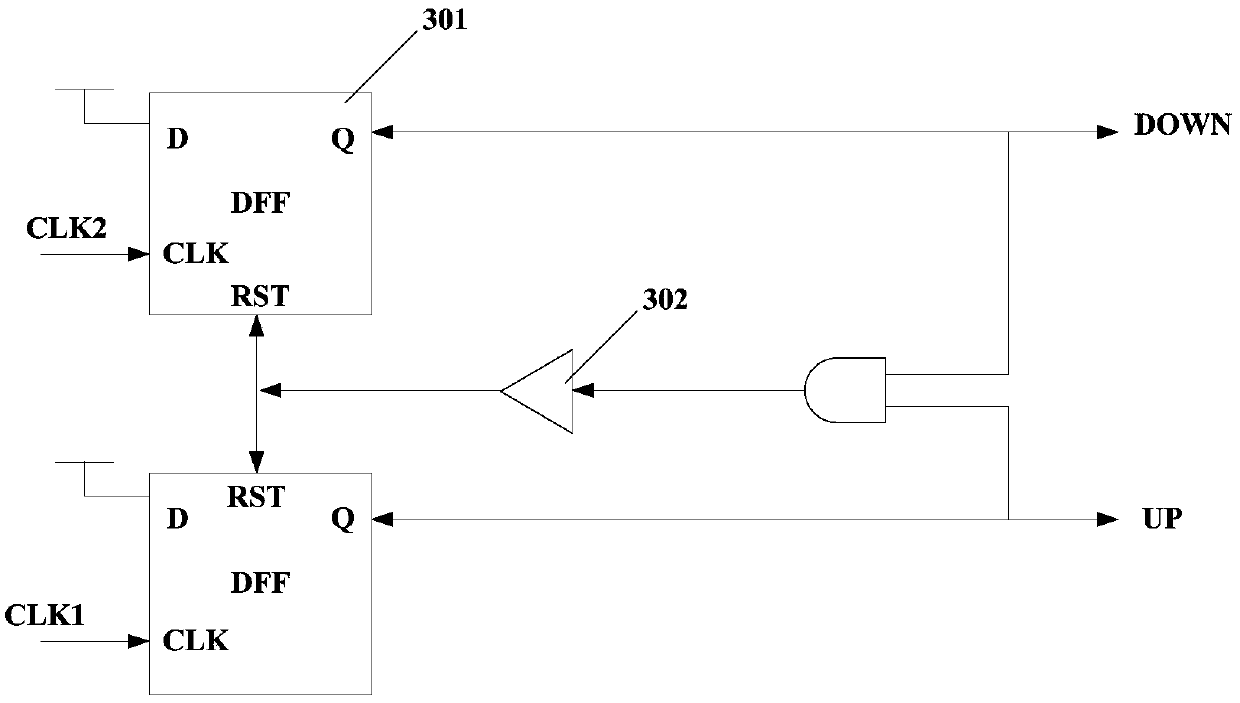
[0049] The frequency divider 101, the frequency divider performs frequency division processing on the externally input reference clock and the output clock of the phase-locked loop, and sends the frequency-divided output clock CLK1 and the frequency-divided reference clock CLK2 to the frequency detector and phase detector 102. The frequency-divided output clock and the reference clock have the same frequency; different frequency division coefficients can be used to ...


PUM


Abstract

The invention relates to an adaptive broadband phase-locked loop circuit, comprising an adaptive driver, a first voltage-current converter, a charge pump and a loop filter. The adaptive driver accumulates phase difference of an output clock of a phase-locked loop and a reference clock, thereby obtaining a rough adjustment control voltage, and outputs the rough adjustment control voltage to the first voltage-current converter. The first voltage-current converter converts the rough adjustment control voltage into a rough adjustment control current. The charge pump takes a mirror current of the rough adjustment control current as a current source, pumps charges into the loop filter or pumps the charges out from the loop filter according to an advancing phase difference signal UP and a laggingphase difference signal DOWN of the output clock through comparison with the input reference clock, and outputs a control voltage signal VCTRL of a voltage-controlled oscillator. According to the phase-locked loop circuit provided by the invention, an output frequency range of the phase-locked loop is expanded, and capture time is reduced. The phase-locked loop circuit can be applied to a clock circuit of a high speed analog-to-digital converter and a high speed serial interface circuit.

Description

technical field [0001] The invention relates to an adaptive broadband phase-locked loop circuit, which belongs to the technical field of integrated circuits and is mainly used to generate a high-speed broadband stable clock. The circuit adjusts the loop bandwidth through an adaptive drive module, shortens the locking time, and is a high-speed serial interface. Provide the clock to ensure the accurate transmission of high-speed data. Background technique [0002] The significance of the phase-locked loop circuit is that it can flexibly give clock signals of various frequencies according to a reference clock signal. Although the crystal oscillator circuit can be used to generate frequency signals in some applications, its inflexibility in adjusting the frequency, the high cost of outputting high-frequency signals, and the speed of the chip interface all limit its application in integrated circuits. The phase-locked loop circuit can provide multiple frequency multiplied signal...

Claims


Application Information

Patent Timeline
IPC IPC(8): H03L7/18H03L7/085H03L7/093H03L7/099
CPCH03L7/085H03L7/093H03L7/099H03L7/18Y02D30/70
Inventor 崔伟张铁良杨松王宗民薛培帆
Owner BEIJING MXTRONICS CORP
Learn More