Determining operating states of an internal combustion engine by means of a generator regulator of an electric machine which is coupled to the internal combustion engine
A technology for internal combustion engines and electric motors, which is applied in the direction of motor starting for engines, motor control, and control of generators, etc. It can solve complex problems and achieve the effect of reducing fuel consumption
Inactive Publication Date: 2019-04-16
ROBERT BOSCH GMBH
View PDF7 Cites 2 Cited by
- Summary
- Abstract
- Description
- Claims
- Application Information
AI Technical Summary
Problems solved by technology
However, such recognition is currently only possible externally, for example by means of the engine control unit or the aforementioned control and regulation unit for controlling the actuation of the clutch, wherein the clutch state thus detected must be forwarded accordingly to the controller of the electric motor, for motor adjustment
However, these methods are very complex, since the corresponding clutch state must first be recognized or determined externally, the determined clutch state is transmitted to the controller of the electric motor, and then, if necessary, the controller executes the corresponding clutch state on the electric motor. The corresponding adjustment pre-determined value of the clutch state
Method used
View moreImage
Smart ImageViewing Examples
Examples
Embodiment Construction
Login to View More PUM
 Abstract
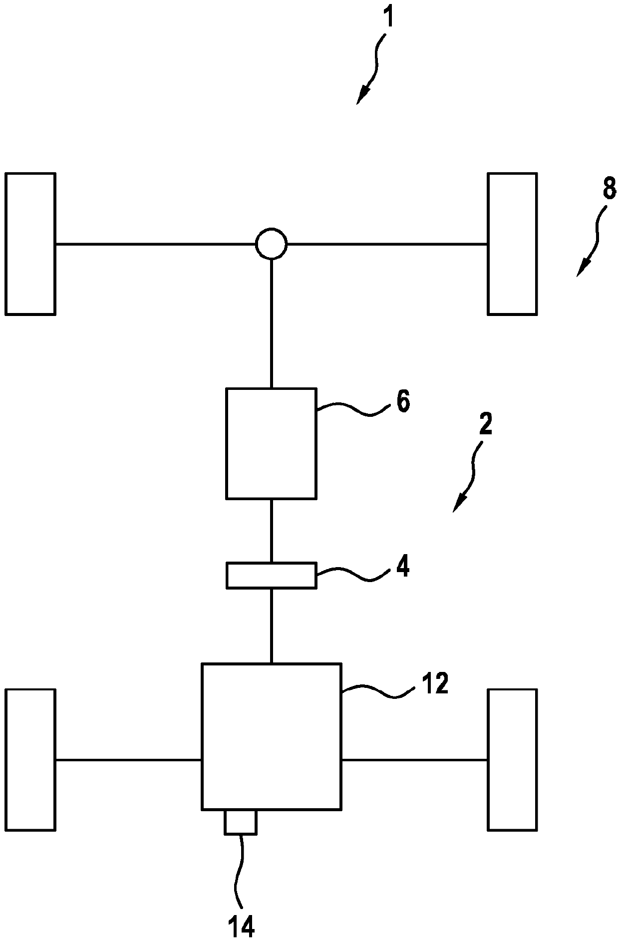
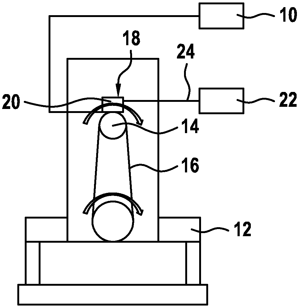
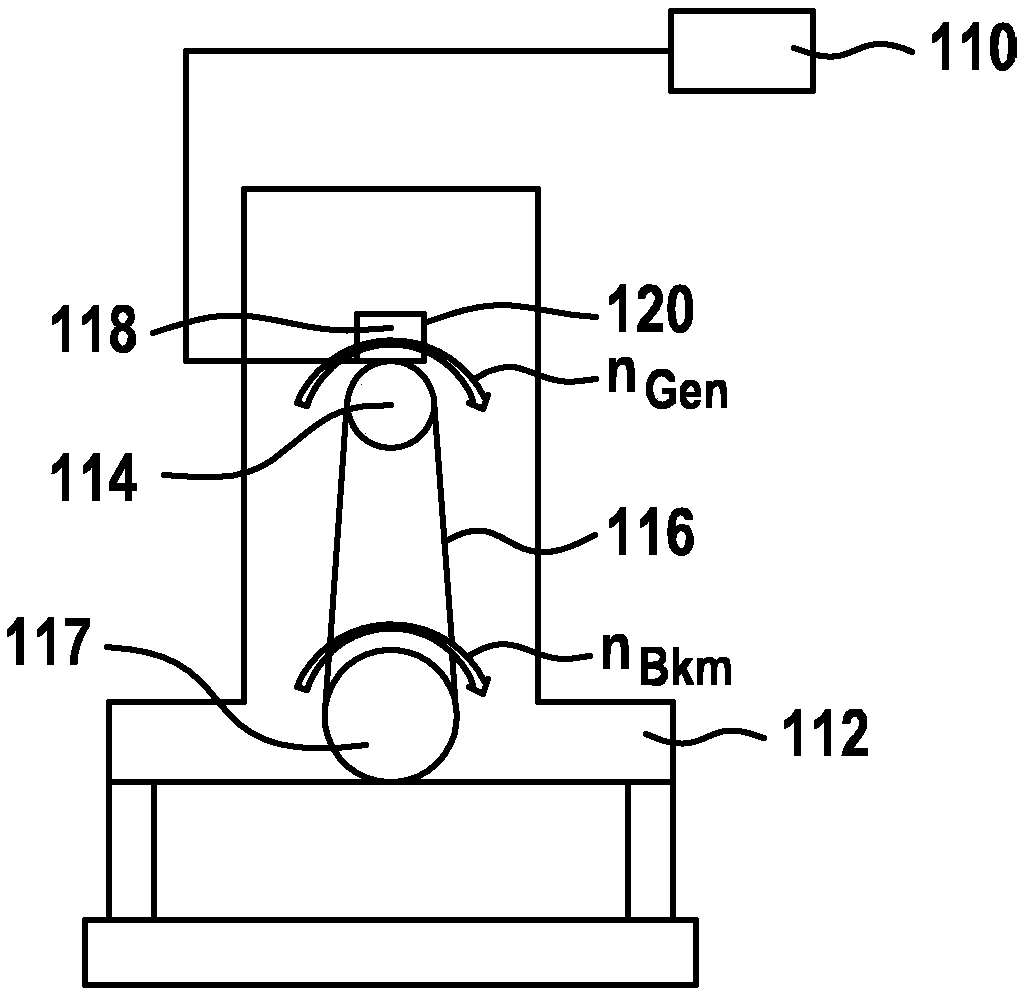
The invention relates to a method for determining a coupling state (128a - 138a) of a drive train (2) of a motor vehicle (1) coupled to a clutch (4) on an internal combustion engine (112). Said methodcomprises the following steps: detecting the temporal course of a rotational speed (n) correlated to the rotational speed (nBKM) of the internal combustion engine (112); detecting at least one speedpattern (128 -138), produced by the internal combustion engine (112), from the temporal course of the rotational speed (nBKM), that has an oscillation (O) with at least one amplitude (A) superimposedover the temporal course of the mean value (DMD) of the rotational speed (nBKM), then it is closed in a coupling state (128a - 138a) when within a time interval ([delta]t), a characteristic change ofthe rotational speed (nBKM) and a characteristic behavior of the amplitudes (A) is detected. Furthermore, the invention relates to a corresponding computing unit (118) which is configured to carry outthe method, to an electric machine comprising the computing unit and to a corresponding computer program for carrying out said method.
Description
technical field The invention relates to a method for determining a clutch state of a drive train coupled to a clutch of an internal combustion engine of a motor vehicle, as well as a computer program and a computing unit for executing the computer program. Background technique To regulate the on-board voltage in a vehicle, electric motors, in particular separately excited electric motors, can be used. They have a regulator that adjusts the field current of the motor according to the on-board voltage. A machine of this type is known from DE 10 2012 204751 A1. Furthermore, it is known to detect the operating state of the internal combustion engine in an engine control device, which recognizes the operating state on the basis of its own set preset value and transfers the corresponding predetermined value associated with the corresponding operating state of the internal combustion engine via a suitable interface Regulator supplied to the motor. The decentralized detection o...
Claims
Login to View More Application Information
Patent Timeline
 IPC IPC(8): F02D41/14F02D41/00F02N11/04G01P3/48G01M15/04H02P9/00H02P29/024F02D41/16F16D48/10
CPCF02D41/0097F02D41/1497F02D2200/101F16D48/06F16D2500/10412F16D2500/3067F16D2500/3163F16D2500/3166F16D2500/5116F16D2500/5118F16D2500/70418F16D2500/7042F16D2500/70689F16D2500/7109F02N2200/041F16D2500/30401H02P9/008H02P9/10H02P9/48H02P29/0241
Inventor U·舒尔茨
Owner ROBERT BOSCH GMBH
Features
- R&D
- Intellectual Property
- Life Sciences
- Materials
- Tech Scout
- Unparalleled Data Quality
- Higher Quality Content
- 60% Fewer Hallucinations
Learn More Browse by: Latest US Patents, China's latest patents, Technical Efficacy Thesaurus, Application Domain, Technology Topic, Popular Technical Reports.
© 2025 PatSnap. All rights reserved.Legal|Privacy policy|Modern Slavery Act Transparency Statement|Sitemap|About US| Contact US: help@patsnap.com


