Ultrasound probe with low frequency, low voltage digital microbeamformer

An ultrasonic probe and digital microwave technology, applied in the field of medical diagnostic ultrasound systems, can solve the problems of increasing the cost and complexity of probe cables

Active Publication Date: 2019-04-16
KONINKLJIJKE PHILIPS NV
View PDF18 Cites 0 Cited by
  • Summary
  • Abstract
  • Description
  • Claims
  • Application Information

AI Technical Summary

Problems solved by technology

However, such an arrangement adds significantly to

Method used


Image

  • Ultrasound probe with low frequency, low voltage digital microbeamformer
  • Ultrasound probe with low frequency, low voltage digital microbeamformer
  • Ultrasound probe with low frequency, low voltage digital microbeamformer

Examples


Embodiment Construction

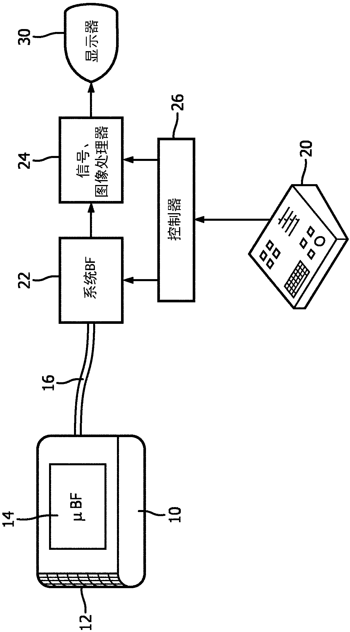
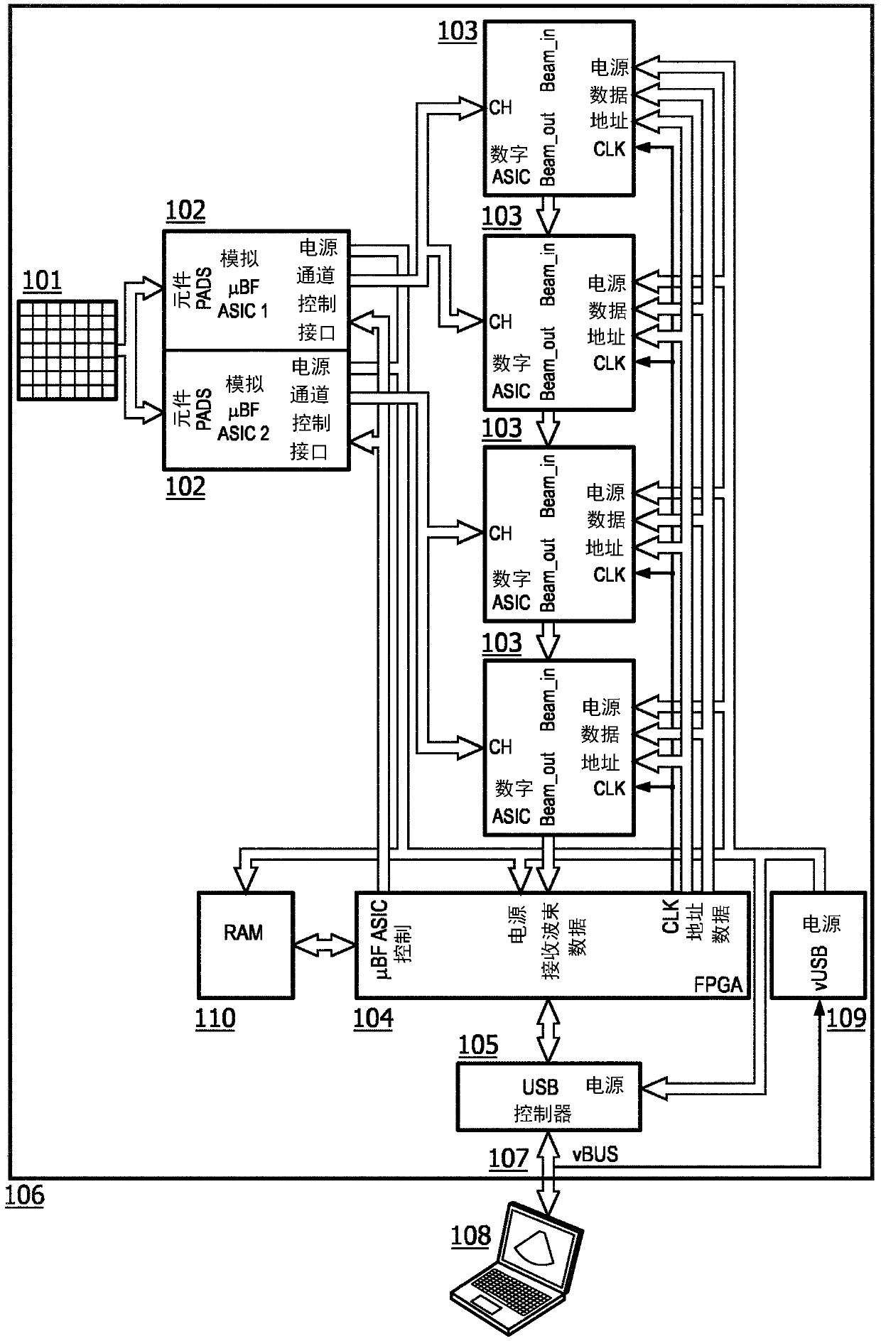
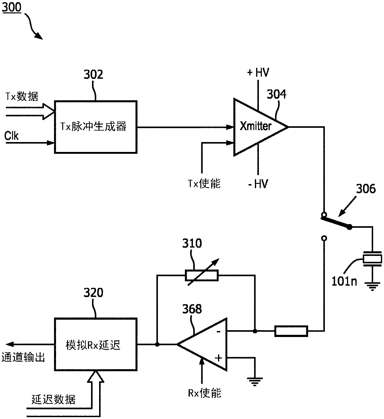
[0019] first reference figure 1 , shows in block diagram form an ultrasound system constructed in accordance with the principles of the present invention. The probe 10 has a two-dimensional array transducer 12, which may be planar or curved, as shown in this example. The transducer may be formed from a MUT device such as a CMUT (Capacitive Micromachined Ultrasonic Transducer) or PVDF, but is preferably formed from a piezoelectric ceramic material such as PZT. The elements of the array are coupled to a digital microbeamformer 14 positioned in the probe behind the transducer array. A microbeamformer is an integrated circuit located in the probe, wherein the beamforming channels are coupled to the elements of the 2D array transducer 12 . The microbeamformer applies timed transmit pulses to individual elements of each set of elements (tiles) of the array to transmit beams in desired directions and to desired focal points in the image field in front of the array. The profile of ...


PUM


Abstract

An ultrasound probe (106) contains an array transducer (101) and a microbeamformer coupled to elements of the array. The microbeamformer comprises analog ASICs (102) with transmitters and amplifiers coupled to elements of the array (101). The microbeamformer also comprises analog to digital converters which convert received echo signals to digital data, and digital beamforming circuitry located indigital ASICs (103). The digital ASICs (103) are clocked at a lower core frequency than that of which the digital integrated circuit process of the digital ASICs (103) is capable, and the digital ASICs (103) are operated at a lower supply voltage than that for which the digital integrated circuit process is designed, both of which reduce power consumption by the microbeamformer.

Description

technical field [0001] The present invention relates to medical diagnostic ultrasound systems, and in particular to ultrasound probes with digital microbeamformers. Background technique [0002] An ultrasound array transducer uses a beamformer to transmit and suitably delay and sum ultrasound echo signals received from elements of the transducer array. The delay is chosen taking into account the direction (steering) and depth of focus of the beams to be formed by the beamformer. After the signals received from each element are appropriately delayed by the channels of the beamformer, the delayed signals are combined to form a beam of coherent echo signals that is appropriately steered and focused. During ultrasound beam transmission, the timing of the actuation of the individual elements is supplemented by receiving delays, steering and focusing the transmitted beam. It is known that the choice of delay can be determined according to the geometry of the array elements as we...

Claims


Application Information

Patent Timeline
IPC IPC(8): G01S7/52G01S15/89G10K11/34
CPCG01S7/52095G01S7/52028G10K11/346G01S7/52096G01S7/5208G01S15/8925H03M1/06H03M3/30
Inventor B·J·萨沃德
Owner KONINKLJIJKE PHILIPS NV
Why Eureka
Try Eureka