Smoking set

A technology for smoking sets and cigarette sticks, which is applied in the field of heating equipment for low-temperature heating of cigarettes, to achieve the effect of lowering the temperature and saving heating energy

Inactive Publication Date: 2019-04-19
SHENZHEN RUXIANGJU TECHCAL DEV LTD +1
View PDF7 Cites 7 Cited by
  • Summary
  • Abstract
  • Description
  • Claims
  • Application Information

AI Technical Summary

Problems solved by technology

[0004] The technical problem to be solved by the present invention is to solve the problem of heat preservation between the smoking set and the accommodating cavity where the cigarette stick is located when heating the cigarette stick, and the heat insulation and cooling problem of the outer wall of the smoking set

Method used


Image

  • Smoking set
  • Smoking set
  • Smoking set

Examples


Embodiment 1

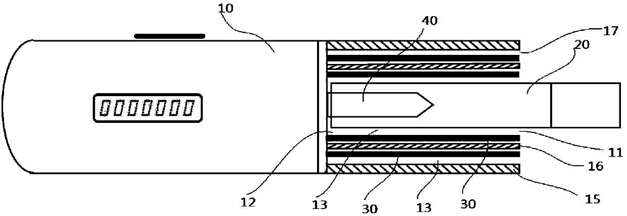
[0016] figure 1 It is a structural schematic diagram of the smoking appliance of this embodiment. The smoking appliance in this embodiment includes a casing 10 and a power supply (not shown in the figure). The housing 10 is in the shape of a strip, which can be a rectangular parallelepiped, a cylinder or other required shapes. A power supply for power supply is provided in the housing 10. Preferably, a control circuit can be added, including but not limited to over-current protection control, temperature control , charge control, discharge control, heating mode control (continuous, pulse, temperature-controlled heating, etc.), etc., and are integrated with the power supply inside the housing 10, and the positive and negative poles of the power supply are electrically connected to the positive and negative poles of the heating device 40. The housing 10 also includes an opening 11, a cavity 12, and an airflow channel 13, and the opening 11 is arranged at the proximal end of the...

Embodiment 2

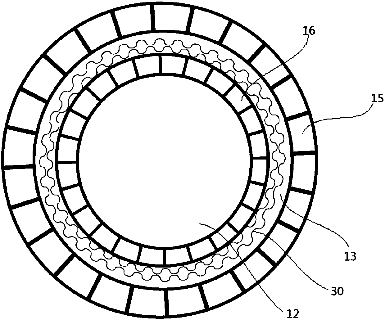
[0022] figure 2It is a structural schematic diagram of the smoking appliance of this embodiment. This embodiment is an extension of Embodiment 1. The difference between the two is that the housing 10 in this embodiment has an interlayer, and at least the tube wall of the housing 10 outside the cavity 12 has an interlayer, for example, the shell outside the cavity 12 The tube wall of the body 10 at least includes a first tube wall 15 outside the housing 10 and a second tube wall 16 inside the housing 10, so that air can flow in from the interlayer, that is, the first tube wall 15 and the second tube wall The gap between the walls 16 constitutes at least a part of said gas flow channel 13 . When the gap between the second tube wall 16 and the cigarette branch 20 is too small to allow the airflow to flow in or the influence on the temperature is negligible, it can be considered that all the airflow flows from the interlayer between the first tube wall 15 and the second tube wal...

Embodiment 3

[0026] Figure 4 It is a structural schematic diagram of the smoking appliance of this embodiment. This embodiment is an extension of Embodiment 1, the difference between the two is that the smoking device in this embodiment also includes a heat sink located in the airflow channel 13 (not shown in the figure, the position coincides with the barrier layer 30) , the heat sink is made of thermally conductive material. For example, the tube wall 14 on the outside of the cavity 12 at least includes a first tube wall 15 outside the housing 10 and a second tube wall 16 inside the housing 10, so that air can flow in from the interlayer, and the cooling fins are arranged on the first tube wall 16. In the gap between the first tube wall 15 and the second tube wall 16 . Preferably, the heat sink is made of metal or ceramic material, that is, it can dissipate heat into the airflow channel 13 at a relatively fast speed in the airflow channel 13, and be taken away when smoking, or it can ...


PUM


Abstract

The invention provides a smoking set, which comprises an elongated shell, a power source, an opening, a cavity and an airflow passage. The power source is arranged in the shell, the end of the shell is provided with the opening, the cavity extends along the shell from the opening longitudinally and used for cigarette storage, and the airflow passage extends longitudinally along a gap between a cigarette and the shell and internally provided with a blocking layer for weakening transverse air flowing. By arrangement of the blocking layer for weakening transverse air flowing in the airflow passage, outward heat diffusion is blocked while a tube wall cooling function is achieved; the blocking layer is intrinsically made from a heat insulation material, the speed of heat diffusion from the storage cavity to the tube wall is sharply decreased while air is partitioned into multiple parts; due to a large contact area between the blocking layer and the flowing airflow, intrinsic heat of the blocking layer and heat of the outer wall of the shell are effectively taken away by air flowing in smoking, so that cooling of the tube wall of the shell is realized.

Description

technical field [0001] The invention relates to heating equipment for low-temperature heating cigarettes, in particular to a heating smoking set for low-temperature heating cigarettes. Background technique [0002] Low-temperature heated (rolled) cigarettes, also known as heat-not-burn (rolled) cigarettes, are more common in the form of cigarettes, hereinafter collectively referred to as low-temperature heated cigarettes, which are different from traditional cigarettes that burn to produce smoke. The low-temperature heating tobacco designed with the idea of ​​"heating without burning" can heat the tobacco leaves just enough to release the flavor without igniting the tobacco leaves. Under normal circumstances, ordinary cigarettes will produce many harmful substances at a high temperature of 350°C to 1000°C, while low-temperature heated tobacco is mostly below 300°C, and because many harmful substances in heated natural or synthetic tobacco products have been It is processed ...

Claims


Application Information

Patent Timeline
Patent Type & Authority Applications(China)
IPC IPC(8): A24F13/00A24F47/00A24F40/20A24F40/485
CPCA24F13/00A24F40/20A24F40/485
Inventor 陈斌林晓航欧阳杰吴扬
Owner SHENZHEN RUXIANGJU TECHCAL DEV LTD
Why Eureka
Try Eureka