Eureka AIR delivers breakthrough ideas for toughest innovation challenges, trusted by R&D personnel around the world.

Machining method for through hole in angular combination device

A combined device and processing method technology, applied in positioning devices, metal processing equipment, metal processing mechanical parts, etc., can solve the problems of through-hole processing quality influence, general through-hole effect, low precision, etc., to avoid repeated calibration and clamping, The effect of reducing professional requirements and improving production efficiency

Active Publication Date: 2019-04-19
JINCHENG NANJING ELECTROMECHANICAL HYDRAULIC PRESSURE ENG RES CENT AVIATION IND OF CHINA
View PDF13 Cites 1 Cited by
  • Summary
  • Abstract
  • Description
  • Claims
  • Application Information

AI Technical Summary

Problems solved by technology

[0002] There are two traditional processing methods for the through-holes of assemblies with angular combination requirements. The first method is to directly process the through-holes in two single pieces according to the final matching angular requirements of the parts, and then press the angular requirements. Assembled together, due to single-piece processing and the accumulation of multiple tolerances in component assembly, the final penetration effect is average and the accuracy is relatively low
The second method is to position and process the through hole in the component at one time. Because this method needs to cut two different parts materials at the same time, it puts forward high requirements on the cutting performance of the tool. In addition, the huge cutting force generated by the cutting tool will cause The slight movement of the contact surface of the two parts will affect the processing quality of the through hole

Method used


Image

  • Machining method for through hole in angular combination device
  • Machining method for through hole in angular combination device

Examples


Embodiment Construction

[0012] The present invention will be further described below in conjunction with accompanying drawing:

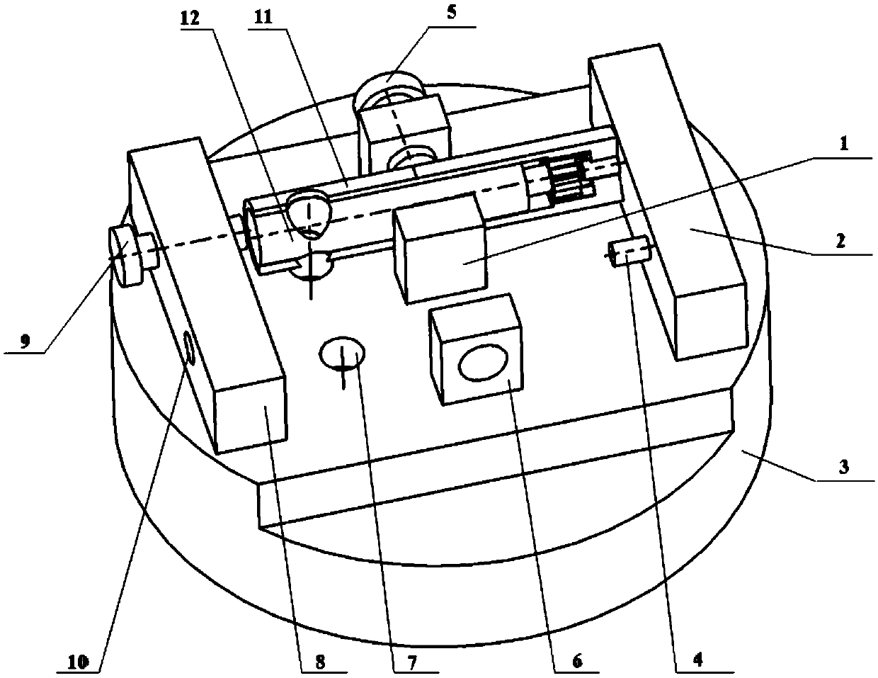
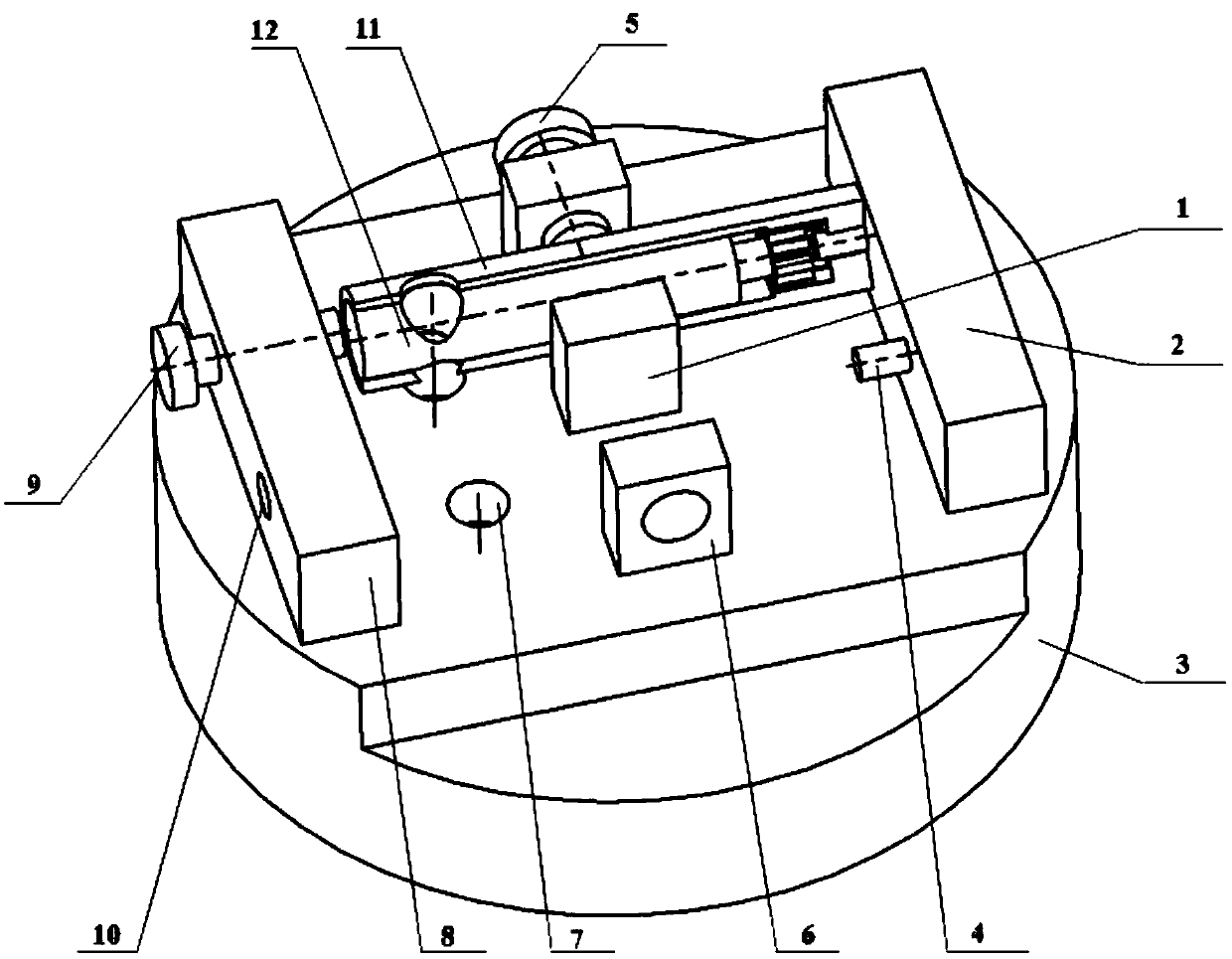
[0013] figure 1 As shown, put assembly one 11 on the base 3, insert the inner hole of assembly one 11 into the end face positioning pin 4, one end of assembly one 11 fits with the end face positioning block 2, and the side of assembly one 11 and the lateral positioning block 1 fit, tighten the lateral compression bolt 5 and the axial compression bolt 9, through the positioning of the end face positioning block 2 and the lateral positioning block 1, the axial compression bolt 9 and the lateral compression bolt 5 are compressed to realize the combination Fixing of piece one 11; machining the through hole of assembly one 11 with a cutter, after the cutter passes through the processing assembly one 11, inserts the avoidance hole 7, withdraws the knife, and completes the processing of the through hole of assembly one 11;

[0014] figure 2 As shown, loosen the axial compressio...


PUM


Abstract

The invention relates to a machining process for a through hole in an angular combination device, in particular to a machining method for a through hole in an angular combination device. A machining clamp for the through hole in the angular combination device is adopted, and machining of the through hole in the angular combination device is achieved on a high-speed milling machine; a first combination part is positioned and clamped through an axial pressing bolt, an end face positioning block, a lateral pressing bolt and a lateral positioning block, and a through hole in the combination part is machined; and an axial positioning bolt is loosened, a second combination part is in inserted, angular combination is achieved, the pressing bolt is screwed, a tool is switched, a high-speed micro cutting milling method is adopted, and a through hole in the second combination part is machined. By means of the method, matching errors produced by through hole separated machining are well avoided,influences produced by different material cutting on a tool are avoided, the cutting movement phenomenon is reduced fundamentally, and the through hole machining quality is effectively improved.

Description

technical field [0001] The invention relates to a processing technology for a through hole of an angular combination device, in particular to a processing method for a through hole of an angular combination device. Background technique [0002] There are two traditional processing methods for the through-holes of assemblies with angular combination requirements. The first method is to directly process the through-holes in two single parts according to the final matching angular requirements of the parts, and then process them according to the angular requirements. Assembled together, due to single-piece processing and the accumulation of multiple tolerances in component assembly, the final penetration effect is average and the accuracy is relatively low. The second method is to position and process the through hole in the component at one time. Because this method needs to cut two different parts materials at the same time, it puts forward high requirements on the cutting pe...

Claims


Application Information

Patent Timeline
Patent Type & Authority Applications(China)
IPC IPC(8): B23P15/00B23Q3/06
CPCB23P15/00B23Q3/062
Inventor 朱鑫波钱均朱雨晗姚素娴杨洪平
Owner JINCHENG NANJING ELECTROMECHANICAL HYDRAULIC PRESSURE ENG RES CENT AVIATION IND OF CHINA
Why Eureka
Eureka Blog
Learn More