Composite cavity box segment liquid-state forming method

A liquid molding and composite material technology, applied in the field of composite material manufacturing, can solve the problems of long injection time, long longitudinal flow length, long resin flow time, etc., achieve fast part forming and manufacturing, improve part forming efficiency, and reduce the number of internal defects Effect

Active Publication Date: 2019-04-19
AVIC BASIC TECH RES INST
View PDF9 Cites 2 Cited by
  • Summary
  • Abstract
  • Description
  • Claims
  • Application Information

AI Technical Summary

Problems solved by technology

[0002] Composite materials are often used in various complex box-section structures. Multi-cavity box-section is the most typical box-section structure, and it is also a difficult structure in the liquid molding process. Generally, the method of end injection is used. This method exists The problems include: 1) The longitudinal flow length is large, the resin flow time is long, the viscosity of the thermosetting resin will increase with time, resulting in poor permeability and easy to form defects at the end; 2) The longitudinal wall of the box section is difficult to penetrate, The fluidity of the resin along the fiber direction is much higher than that in the Z direction. When the thickness of the part is large, it will be difficult to penetrate; 3) The injection time is long and the manufacturing cost is high
The liquid molding of composite materials generally only sets flow channels on one side or both sides of the part, which can meet the requirements of the manufacture of small and medium-sized composite parts. The situation of penetration affects the quality of parts

Method used


Image

  • Composite cavity box segment liquid-state forming method
  • Composite cavity box segment liquid-state forming method
  • Composite cavity box segment liquid-state forming method

Examples


Embodiment 1

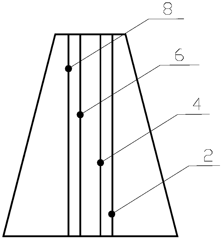
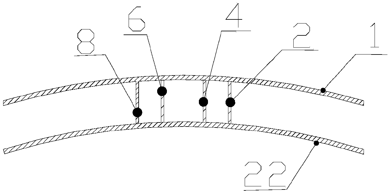
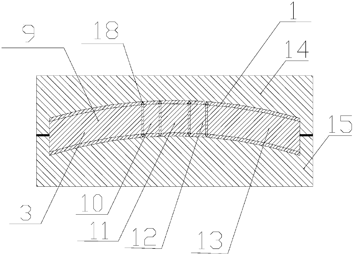
[0030] Taking the composite three-chamber box section as an example, figure 1 Reveals a schematic diagram of the top view of the three-cavity box section of the composite material, figure 2 The schematic diagram of the front section of the composite three-cavity box section part is revealed, image 3 The schematic diagram of the assembly of the composite three-cavity box-section green body, core mold, upper mold, and lower mold is revealed, Figure 4 A schematic cross-sectional view of the secondary runner is revealed, Figure 5 for Figure 4 The side view of the secondary flow channel, distribution of flow holes 19 on each side, Image 6 The schematic diagram of the bottom mold is disclosed, in which the sprue 16 is distributed according to the cross-section of the part, Figure 7 It is the longitudinal wall 1 of the cavity and its local schematic diagram, Figure 8 A schematic diagram of the top mold.

[0031] The main body of the composite material three-cavity box s...


PUM

PropertyMeasurementUnit
thicknessaaaaaaaaaa

Abstract

The invention discloses a composite cavity box segment liquid-state forming method. The method comprises following steps of skin and core mold blank body paving and pasting, core mold and secondary runner assembling, upper skin paving and pasting, upper mold and other mold assembly, resin injection, and mold releasing. The forming method is used for liquid-state forming of a composite cavity box segment. Compared with the prior art, the method solves the problems that the injection path is long, the period is long, and deficient glue defects are easily caused, large resin viscosity and difficult injection caused by long-time injection and end injection can be avoided, part manufacturing efficiency is improved, and the manufacturing cost is reduced.

Description

technical field [0001] The invention relates to the technical field of composite material manufacturing, in particular to a liquid forming method for a cavity box segment of a composite material. Background technique [0002] Composite materials are often used in various complex box-section structures. Multi-cavity box-section is the most typical box-section structure, and it is also a difficult structure in the liquid molding process. Generally, the method of end injection is used. This method exists The problems include: 1) The longitudinal flow length is large, the resin flow time is long, the viscosity of the thermosetting resin will increase with time, resulting in poor permeability and easy to form defects at the end; 2) The longitudinal wall of the box section is difficult to penetrate, The fluidity of the resin along the fiber direction is much higher than that in the Z direction. When the thickness of the part is large, it will be difficult to penetrate; 3) The inje...

Claims


Application Information

Patent Timeline
Patent Type & Authority Applications(China)
IPC IPC(8): B29C70/44
CPCB29C70/443
Inventor 崔海超翟全胜叶宏军李义苗春卉刘立朋张晨乾
Owner AVIC BASIC TECH RES INST
Why Eureka
Try Eureka