SSVEP brain-computer interface asynchronous control system
A technology of asynchronous control and machine interface, applied in the field of human-computer interaction, can solve the problems of sending instructions not completely according to the user's intention and limited application, and achieve the effect of high practical value, fast response speed, and simple strategy
- Summary
- Abstract
- Description
- Claims
- Application Information
AI Technical Summary
Problems solved by technology
Method used
Image
Examples
Embodiment 1
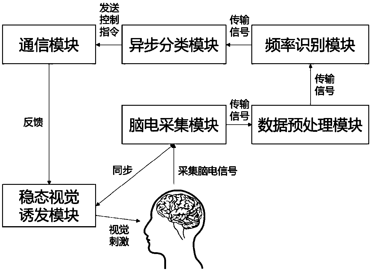
[0062] The structure of an asynchronous control system of SSVEP brain-computer interface is as follows: figure 1 As shown, it includes the following parts: steady-state evoked visual stimulation module, EEG acquisition module such as EEG electrodes and EEG amplifiers, data preprocessing module, frequency identification module, and asynchronous classification module.
[0063] The use of this system involves the following sequential steps:
[0064] S101. The stimulation frequency adopts (but not limited to) 8, 9, 10, 11, 12, 13, 14, 15 Hz, and the user watches the target stimulation according to the needs to generate scalp EEG signals;
[0065] S102. The EEG acquisition channel adopts (but not limited to) the leads POz, Oz, O1, O2, PO3, PO4, PO5, and PO6 located in the occipital area, and collects the top of the head signal as a reference, and the front of the forehead as a grounding channel; electrode cap acquisition Scalp EEG signal, after the EEG amplifier, transmits the sig...
Embodiment 2
[0072] The structure of an asynchronous control system of SSVEP brain-computer interface is as follows: figure 1 As shown, it includes the following parts: steady-state evoked visual stimulation module, EEG acquisition module such as EEG electrodes and EEG amplifiers, data preprocessing module, frequency identification module, and asynchronous classification module.
[0073] The use of this system involves the following sequential steps:
[0074] S201. Stimulation frequency adopts (but not limited to) 8, 9, 10, 11, 12, 13, 14, 15Hz, and the user focuses on the target stimulation as needed to generate scalp EEG signals;
[0075] S202. The EEG acquisition channel adopts (but not limited to) the leads POz, Oz, O1, O2, PO3, PO4, PO5, and PO6 located in the occipital area, and collects the top of the head signal as a reference, and the front of the forehead as a grounding channel; electrode cap acquisition The scalp EEG signal is transmitted to the data preprocessing module inside...
Embodiment 3
[0083] The structure of an asynchronous control system of SSVEP brain-computer interface is as follows: figure 1 As shown, it includes the following parts: steady-state evoked visual stimulation module, EEG acquisition module such as EEG electrodes and EEG amplifiers, data preprocessing module, frequency identification module, and asynchronous classification module.
[0084] The use of this system involves the following sequential steps:
[0085] S301. The stimulation frequency adopts (but not limited to) 8, 9, 10, 11, 12, 13, 14, 15Hz, and the user watches the target stimulation according to the needs to generate scalp EEG signals;
[0086] S302. The EEG acquisition channel adopts (but not limited to) the leads POz, Oz, O1, O2, PO3, PO4, PO5, and PO6 located in the occipital area, and collects the top of the head signal as a reference, and the front of the forehead as a grounding channel; electrode cap acquisition The scalp EEG signal is transmitted to the data preprocessing...
PUM
 Abstract
Description
Claims
Application Information
 - R&D
- Intellectual Property
- Life Sciences
- Materials
- Tech Scout
- Unparalleled Data Quality
- Higher Quality Content
- 60% Fewer Hallucinations
Browse by: Latest US Patents, China's latest patents, Technical Efficacy Thesaurus, Application Domain, Technology Topic, Popular Technical Reports.
© 2025 PatSnap. All rights reserved.Legal|Privacy policy|Modern Slavery Act Transparency Statement|Sitemap|About US| Contact US: help@patsnap.com


