Flat chamfering machine

A technology of chamfering machine and flat plate, which is used in metal processing machinery parts, clamping, supporting and other directions, can solve the problems of flat plate deviation, the guide wheel cannot be actively rotated, and the accuracy of work is affected.

Pending Publication Date: 2019-04-23
ZHEJIANG AOTAI MACHINE MFG
View PDF6 Cites 4 Cited by
  • Summary
  • Abstract
  • Description
  • Claims
  • Application Information

AI Technical Summary

Problems solved by technology

[0002] The traditional chamfering machine can only chamfer the circular pipe port, but it is not suitable for the chamfering of the flat plate, so there is a flat chamfering machine for chamfering the flat plate, the flat chamfering machine includes The motor, the switch and the chamfering knife, the chamfering knife is connected with the output shaft of the motor through the cutter head shaft, and the positioning plate and the guide plate which form a certain angle with each other are arranged on both sides of the chamfering knife, and the positioning and rotation on the guide plate are provided with a guide One side of the flat plate is parallel to the positioning plate, and the other side is in conflict with the guide wheel. Under the action of the guide wheel, the flat plate is conveyed more smoothly. The chamfering knife chamfers the flat plate. It is very flat, and the guide wheel cannot automatically adjust the position, so that there is a large deviation in the chamfering of the flat plate, which affects the machining accuracy, and the guide wheel cannot be actively rotated, and cannot drive the automatic transmission of the flat plate, which is inconvenient to operate.

Method used


Image

  • Flat chamfering machine
  • Flat chamfering machine
  • Flat chamfering machine

Examples


Embodiment Construction

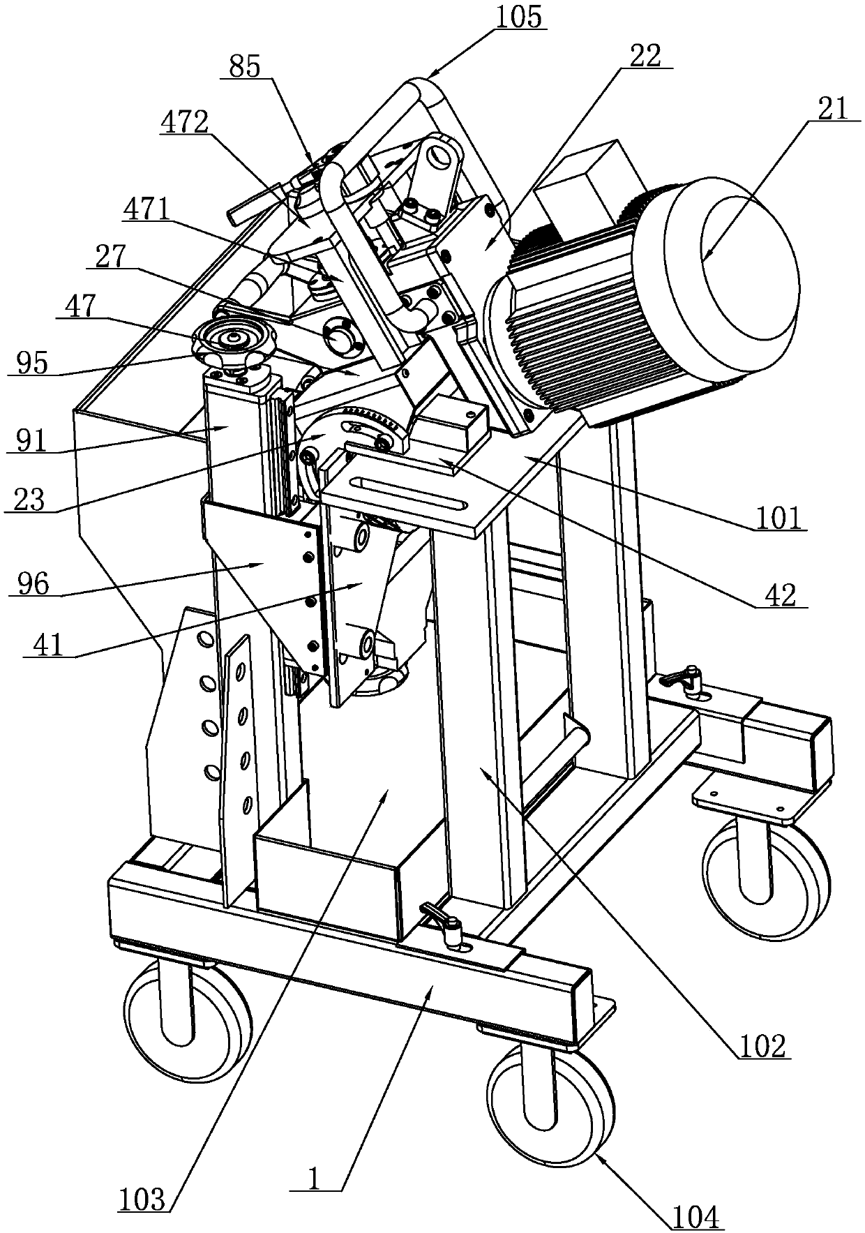
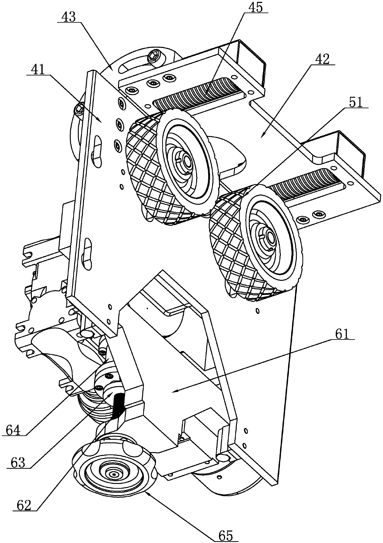
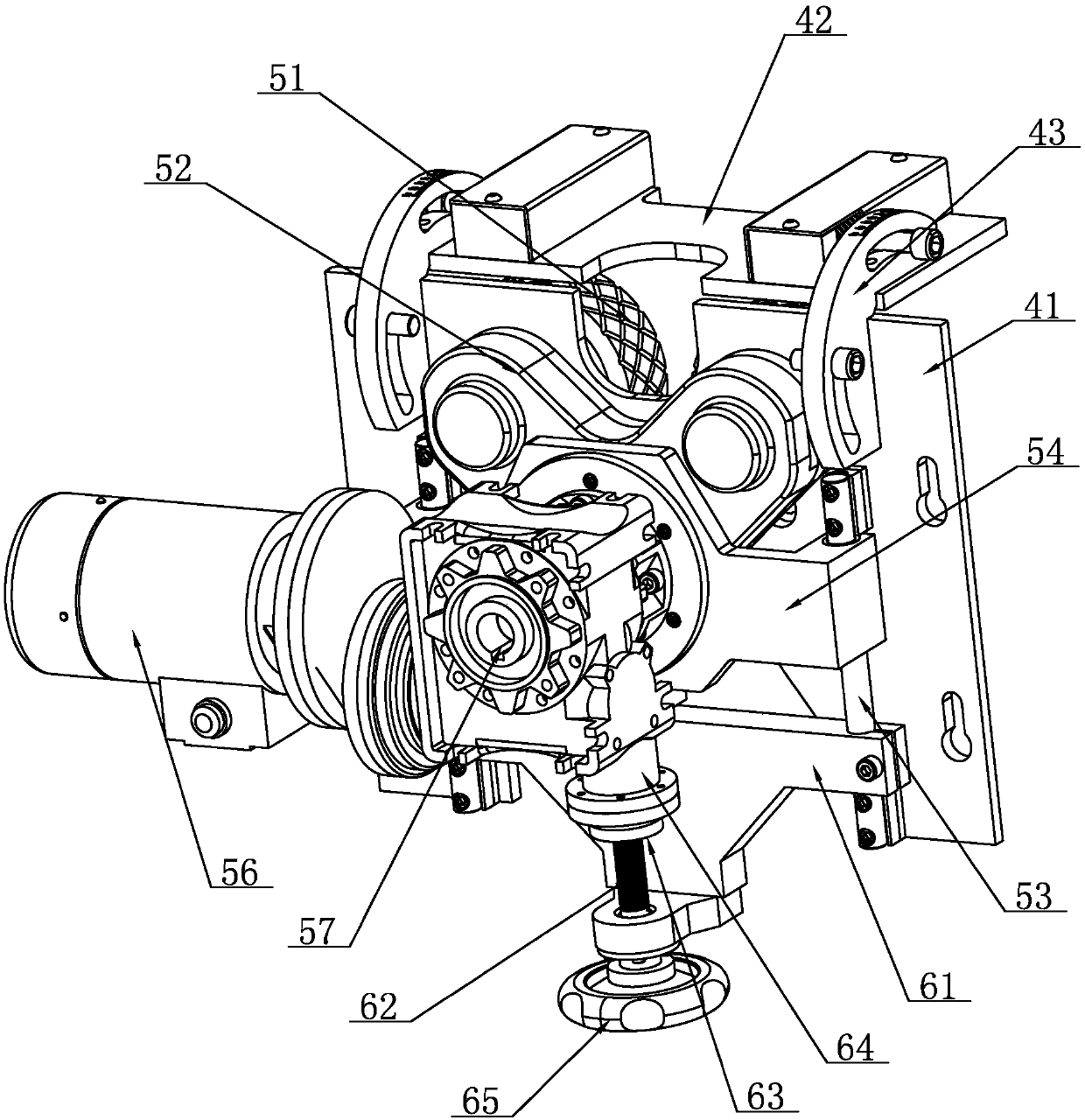
[0037] Such as Figure 1-Figure 12 As shown, a flat chamfering machine includes a frame 1, a first motor 21 and a chamfering knife 3, the first motor 21 is arranged on the frame 1 through a motor mount 22, and the chamfering knife 3 is rotated and installed on the motor On the seat 22, the output shaft of the first motor 21 is linked with the chamfering knife 3. The frame 1 is provided with a positioning plate 41 and a guide plate 42. The positioning plate 41 is installed on the frame 1, and the positioning plate 41 and the guide plate 42 are fixed. Connected, the first motor 21 is located above the guide plate 42, the end of the chamfering knife 3 extends between the positioning plate 41 and the guide plate 42, the motor mounting seat 22 is reversibly arranged on the positioning plate 41, and the positioning plate 41 is provided with There is a roller assembly for conveying flat plates, the roller assembly includes a first roller 51 and a roller seat 52, the first roller 51 i...


PUM


Abstract

The invention relates to a flat chamfering machine. The flat chamfering machine comprises a frame, a first motor and a chamfering knife; the first motor is arranged on the frame through a motor mounting seat; a positioning plate and a guiding plate are arranged on the frame; the positioning plate is arranged on the frame; the end of the chamfering knife extends to the middle of the positioning plate and the guiding plate; the positioning plate is provided with a roller assembly, and the roller assembly comprises a first roller and a roller seat; the first roller is arranged on the roller seat;the first roller and the roller seat are correspondingly arranged on two sides of the positioning plate; and the roller seat is provided with a driving assembly capable of driving the first roller torotate; the roller seat is slidably arranged on the positioning plate in the vertical direction; an adjusting assembly is arranged between the roller seat and the positioning plate for adjusting theposition of the roller seat; the adjusting assembly comprises an adjusting bracket; the adjusting bracket is fixedly arranged on the positioning plate; and a spring is arranged between the adjusting bracket and the roller seat for the roller seat to be pressed and moved. The above scheme facilitates automatic transmission of flat plates and the processing precision is higher.

Description

technical field [0001] The invention relates to a plate chamfering machine. Background technique [0002] The traditional chamfering machine can only chamfer the circular pipe port, but it is not suitable for the chamfering of the flat plate, so there is a flat chamfering machine for chamfering the flat plate, the flat chamfering machine includes The motor, the switch and the chamfering knife, the chamfering knife is connected with the output shaft of the motor through the cutter head shaft, and the positioning plate and the guide plate which form a certain angle with each other are arranged on both sides of the chamfering knife, and the positioning and rotation on the guide plate are provided with a guide One side of the flat plate is parallel to the positioning plate, and the other side is in conflict with the guide wheel. Under the action of the guide wheel, the flat plate is conveyed more smoothly. The chamfering knife chamfers the flat plate. It is very flat, and the g...

Claims


Application Information

Patent Timeline
Patent Type & Authority Applications(China)
IPC IPC(8): B23D79/00B23Q5/10B23Q5/40B23Q11/00B23Q3/12
CPCB23D79/00B23Q3/12B23Q5/10B23Q5/40B23Q11/00
Inventor 项彬宸项光春项玉振
Owner ZHEJIANG AOTAI MACHINE MFG
Why Eureka
Try Eureka