Tail gas heat recovery system of polycrystalline silicon production equipment and operation method thereof

A production equipment and heat recovery technology, applied in lighting and heating equipment, silicon, waste heat treatment, etc., can solve the problems of ineffective use of steam, complex system control, and difficulty in protecting heat supply, so as to improve the efficiency of heat recovery and utilization, reduce The effect of material cost

Pending Publication Date: 2019-04-23
JIANGSU DONGFANG RUIJI ENERGY EQUIP CO LTD
View PDF2 Cites 4 Cited by
  • Summary
  • Abstract
  • Description
  • Claims
  • Application Information

AI Technical Summary

Problems solved by technology

[0005] 1. Although directly using the heat of high-temperature exhaust gas to vaporize and heat the inlet temperature of the feed can reduce the power consumption of the reduction furnace system and achieve energy-saving effects, but the flow rate of the exhaust gas in the reduction production process is dynamic, and it is difficult to protect a stable heat supply, especially The reason is that the heat of the exhaust gas cannot meet the heat required by the system when starting up and stopping the furnace, so usually the system needs to add an auxiliary heat source, which makes the control of the system relatively complicated;
[0006] 2. Although the existing tail gas heat recovery method has been able to solve part of the low-temperature return water problem, the existing heat recovery system still cannot make full use of the heat energy generated by the reduction furnace, and the low-pressure steam generated cannot be directly used for polysilicon production. The high temperature of the return water Water temperature cannot flash high-grade steam, and low-grade steam cannot be effectively utilized in large process systems of polysilicon factories

Method used


Image

  • Tail gas heat recovery system of polycrystalline silicon production equipment and operation method thereof

Examples


Embodiment Construction

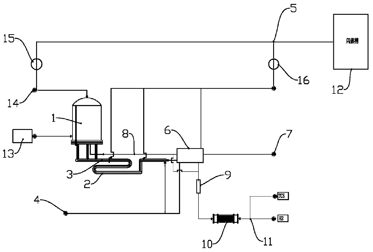
[0025] Such as figure 1 As shown, the tail gas heat recovery system of the polysilicon production equipment includes a reduction furnace 1 for polysilicon production, the tail gas outlet of the reduction furnace is connected to the tail gas delivery pipeline 3, and the tail gas delivery pipeline 3 has two sections that adopt serpentine jacket pipes The jacketed pipe 2 of the heating device, the inlet and outlet of the jacketed pipe 2 are respectively connected to the cooling water inlet 4 and the high temperature water outlet 5 through the second high temperature pump 16; the tail gas delivery pipeline 3 is connected to the tail gas discharge through a heat exchanger 6 port 7; the heat exchanger 6 is provided with a heat exchange medium inlet and an outlet, respectively connected to the cooling water inlet 4 and the high-temperature water outlet 5, so that the tail gas and the cooling water can exchange heat in the heat exchanger; the raw material inlet of the reduction furnace...


PUM


Abstract

The invention relates to a tail gas heat recovery system of polycrystalline silicon production equipment and an operation method thereof. The tail gas heat recovery system of the polycrystalline silicon production equipment comprises a reducing furnace, the tail gas outlet of the reducing furnace is connected with a tail gas conveying pipe with a jacketed pipe, and the jacketed pipe is connected with a cooling water inlet and a high-temperature water outlet; the tail gas conveying pipe is connected with a tail gas exhaust outlet through a heat exchanger; the heat exchange medium inlet and theheat exchange medium outlet of the heat exchanger are connected with the cooling water inlet and the high-temperature water outlet respectively; the raw material inlet pipe of the reducing furnace isconnected with a total feeding port via a buffer and a vaporizer; two branches are arranged between the buffer and the raw material inlet pipe of the reducing furnace, one branch is directly connectedwith the raw material inlet pipe, and the other branch passes through the heat exchanger and exchanges heat with tail gas and high-temperature water in the heat exchanger and is then connected with the raw material inlet pipe; the high-temperature water outlet is communicated with a flash tank for producing saturated vapor. The tail gas heat recovery system of the polycrystalline silicon production equipment can efficiently recycle heat of tail gas produced during polycrystalline silicon production, achieve stable heat output and produce vapor applicable to polycrystalline silicon productionprocesses.

Description

technical field [0001] The invention relates to polysilicon production equipment, in particular to a tail gas heat recovery system and operation method of polysilicon production equipment. Background technique [0002] At present, the main process technology for producing polysilicon is the improved Siemens method: after the purified high-purity trichlorosilane and hydrogen are mixed in proportion, they are passed into the polysilicon reduction furnace at a certain temperature and pressure, and the energized high-temperature silicon core The deposition reaction produces polysilicon and produces high-temperature reduction tail gas. The tail gas such as tetrachlorosilane, trichlorosilane, hydrogen chloride, and hydrogen in the reduction tail gas is cooled, separated and recovered, and then returned to the raw material for recycling. During the above reaction process on the silicon core in the reduction furnace, it is necessary to use electric energy to heat the reaction temper...

Claims


Application Information

Patent Timeline
Patent Type & Authority Applications(China)
IPC IPC(8): C01B33/03F27D17/00F27D9/00
CPCF27D9/00F27D17/004C01B33/03F27D2017/006F27D2009/0013Y02P10/25Y02P20/10
Inventor 洪钰张云天
Owner JIANGSU DONGFANG RUIJI ENERGY EQUIP CO LTD
Why Eureka
Try Eureka