
Water-oil separation container for swill

A water-oil separation and container technology, which is applied in liquid separation, separation methods, liquid separation auxiliary equipment, etc., can solve the problems of large water content in stagnant water, lack of stagnant oil treatment equipment, and high transportation costs, and achieve the effect of rapid water-oil separation

Inactive Publication Date: 2019-04-23
曹美乐
View PDF6 Cites 0 Cited by
  • Summary
  • Abstract
  • Description
  • Claims
  • Application Information

AI Technical Summary

Problems solved by technology

However, in the prior art, due to the high water content of hogwash, high transportation costs, and high post-treatment costs, there is a lack of corresponding hogwash oil treatment equipment. In order to prevent hogwash oil from flowing into the market, there is an urgent need for a water-oil separation container that quickly collects hogwash oil.

Method used


Image

  • Water-oil separation container for swill
  • Water-oil separation container for swill
  • Water-oil separation container for swill

Examples


Embodiment 2

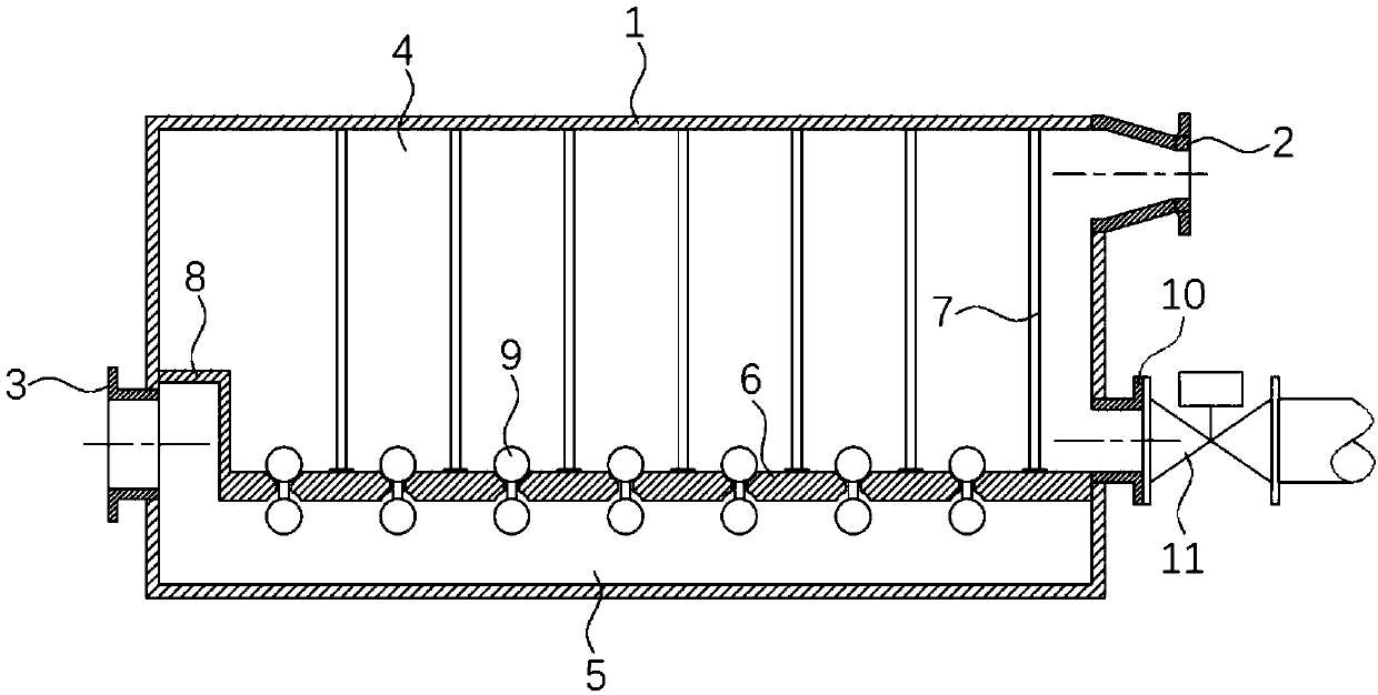
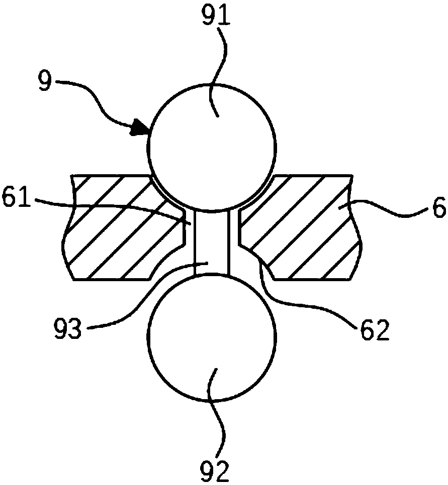
[0030] On the basis of the first embodiment above, the first sphere 91 is made of a permanent magnet, and the separator 6 is made of a ferromagnetic material. The first sphere 91 can open the through hole 61 in water and a liquid with a specific gravity greater than 1.

[0031] Since the first sphere 91 is made of permanent magnet material, the first sphere 91 is attracted to the separator 6 made of ferromagnetic material, thereby increasing the sealing performance and preventing the first sphere 91 from moving freely under the washing of the liquid.

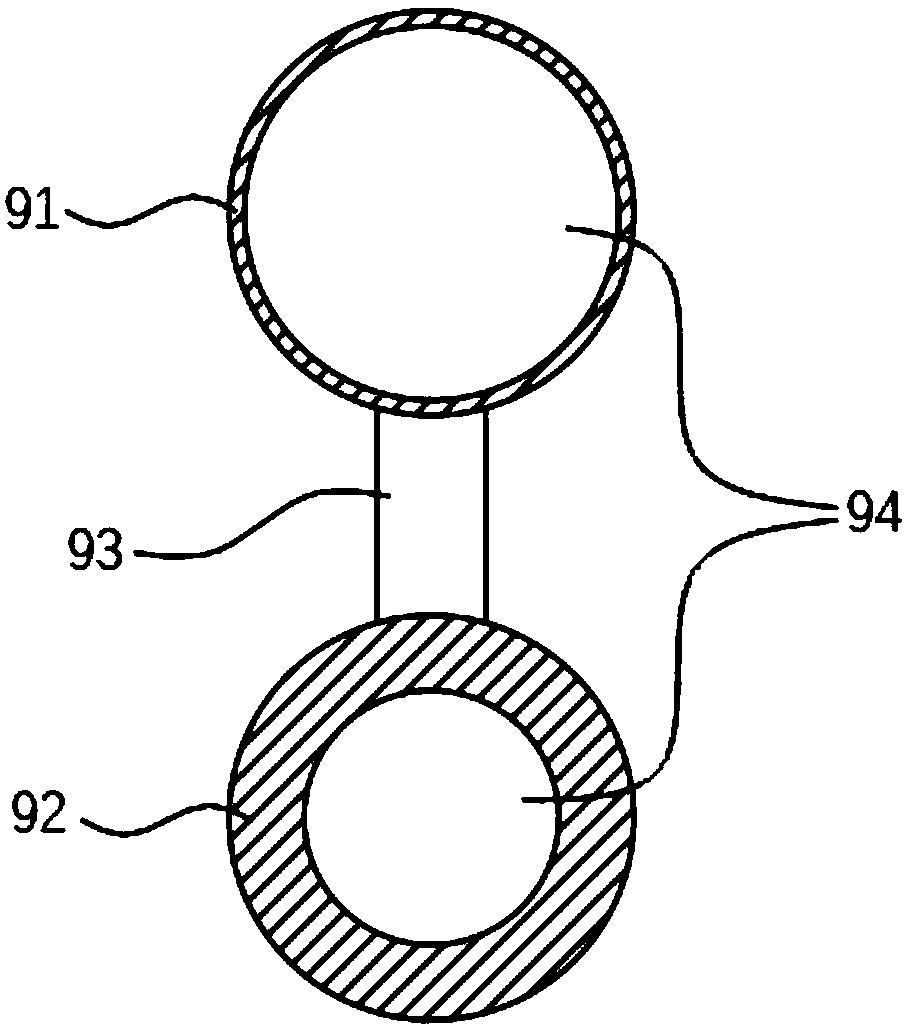
[0032] It is worth mentioning that buoyancy compensation can be performed by changing the thickness of the second sphere 92 to reduce gravity, so that the first sphere 91 can float in the oil layer against the magnetic force of the separator 6 .

Embodiment 3

[0034] On the basis of the second embodiment above, a plurality of anti-turbulence rods 7 perpendicular to the two are fixedly connected between the top of the partition 6 and the inner top of the container 1 .

[0035] Preferably, the anti-turbulence rod 7 is located between two adjacent through holes 61 .

[0036] Because the speed of the sewage from the mixed liquid inlet pipe 2 is too fast, the anti-turbulence rod 7 reduces the speed at which the mixed liquid inlet pipe 2 enters the container 1, and the turbulent flow becomes transitional flow or laminar flow under the blocking effect of the anti-turbulence rod 7 On the one hand, it facilitates the stratification of water and oil, and on the other hand, it can also prevent the first ball 91 from being washed and displaced, which can improve the efficiency of sewage treatment.


PUM


Abstract

The invention discloses a water-oil separation container for swill. The water-oil separation container comprises a container body, the upper end of the container body is communicated with a mixed liquid incoming pipe while the bottom end of the same is communicated with a water discharging pipe and an oil discharging pipe, an electromagnetic valve is arranged on the oil discharging pipe, a partition capable of separating the water discharging pipe from the mixed liquid incoming pipe and the oil discharging pipe is arranged at the bottom end of the container body, a retaining plate is integrally formed on one side, close to the water discharging pipe, of the partition, and multiple through holes are formed in the partition equidistantly; an oil-water isolation member capable of controllingopening and closing of the corresponding through hole is movably arranged in each through hole; specific gravity of water is defined as that each through hole can be opened when the corresponding oil-water isolation member is in the water and liquid greater than in specific gravity and can be closed when the corresponding oil-water isolation member is in oil and liquid smaller than in specific gravity. The water-oil separation container can isolate oil rather than water, the circumstance that conventional treatment ponds occupy big space is avoided, and the water-oil separation container is quick, stable and effective in water-oil separation.

Description

technical field [0001] The invention relates to the technical field of sewage treatment, in particular to a water-oil separation container for hogwash. Background technique [0002] Hogwash oil is miscellaneous oil, and it has a better taste when added to food. When the huge profits of illegal oil refining are not equal to the cost of minor violations, people who are greedy for profit will use hogwash oil as a tool to make money. Hogwash oil flows to the dining table. is an open secret. However, in the prior art, due to the large water content of hogwash, high transportation costs, and high post-treatment costs, there is a lack of corresponding hogwash oil treatment equipment. In order to prevent hogwash oil from flowing into the market, there is an urgent need for a water-oil separation container that quickly collects hogwash oil. Contents of the invention [0003] The purpose of the present invention is in order to solve above-mentioned problem, and proposes a kind of h...

Claims


Application Information

Patent Timeline
IPC IPC(8): C02F1/40B01D17/032B01D17/12
CPCB01D17/0214B01D17/12C02F1/40
Inventor 曹美乐
Owner 曹美乐
Learn More