Energy output system and method applied to urea plant

A technology for urea plant and energy output, which is applied in the direction of pump device, steam engine device, non-variable pump, etc., to achieve the effect of low system investment, high output efficiency and good economic benefits

Pending Publication Date: 2019-04-23
苏州欧拉透平机械有限公司
View PDF12 Cites 2 Cited by
  • Summary
  • Abstract
  • Description
  • Claims
  • Application Information

AI Technical Summary

Problems solved by technology

[0003] How to use the carbon dioxide gas in the subcritical state in the existing urea plant to realize the Brayton cycle, so as to realize the efficient output of energy, there is no relevant research results in this regard.

Method used


Image

  • Energy output system and method applied to urea plant
  • Energy output system and method applied to urea plant

Examples


Embodiment 1

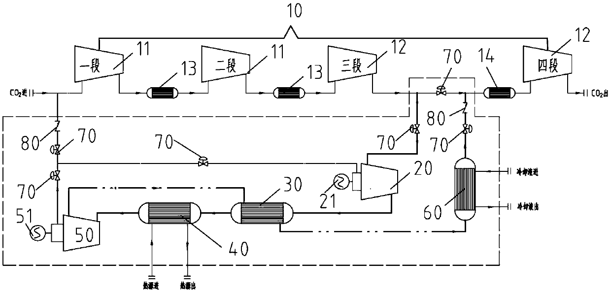
[0025] Embodiment 1: as figure 1 As shown, an energy output system applied to a urea plant, the urea plant includes a carbon dioxide multi-stage centrifugal compressor 10, the multi-stage centrifugal compressor includes several low-pressure sections 11 and several high-pressure sections 12, two adjacent sections There is an intercooler between them, and a subcritical carbon dioxide output pipeline and an input pipeline are arranged between the terminal high-pressure section and the secondary terminal high-pressure section, and the output pipeline is connected to the supercharger 20, the preheater 30, the heating 40 and expander 50, the carbon dioxide gas after the work done by the expander passes through the preheater 30, the cooler 60, the subcritical carbon dioxide input pipeline into the inter-stage cooler, and finally enters the terminal high-pressure section. The present invention utilizes the existing urea synthesis device to realize the Brayton cycle, so as to realize e...

Embodiment 2

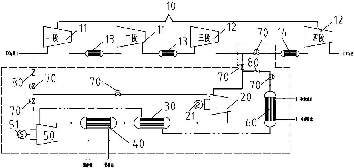
[0029] Embodiment 2: as figure 2 As shown, the only difference from Example 1 is that the carbon dioxide gas after the work done by the expander passes through the preheater 30, the cooler 60, and the subcritical carbon dioxide input pipeline to return to the supercharger 20 for recycling, that is, after the booster After pressurization, the compressor passes through the preheater 30 and the heater 40 and then enters the expander to do work. In this embodiment, after a certain amount of carbon dioxide is extracted from the urea plant, the carbon dioxide gas will no longer return to the urea synthesis system, but will be added in the newly added The system formed by the equipment is recycled, and the urea plant supplements the small amount of carbon dioxide gas lost during the operation of the system of this embodiment through the regulating valve 70.

[0030] Operation process of the present invention: the steps are as follows:

[0031] Step 1: Lead the subcritical carbon diox...


PUM


Abstract

The invention relates to an energy output system applied to a urea plant. The urea plant comprises a carbon dioxide multi-stage centrifugal compressor. The multi-stage centrifugal compressor comprisesa plurality of low-pressure stages and a plurality of high-pressure stages. An inter-stage cooler is arranged between every two adjacent stages. A subcritical carbon dioxide output pipeline and a subcritical carbon dioxide input pipeline are arranged between the terminal high-pressure stage and the penultimate high-pressure stage. The output pipeline enables a supercharger, a preheater, a heaterand an expansion machine to be connected in sequence. Carbon dioxide gas working through the expansion machine sequentially passes through the preheater, a cooler, the subcritical carbon dioxide inputpipeline to enter the inter-stage coolers, and finally enters the terminal high-pressure stage. According to the energy output system applied to the urea plant, under the circumstances that main technologies and equipment of an original urea synthesizing plant are unchanged, the high efficiency of the brayton cycle principle is utilized, the system is made to be low in input and high in energy output efficiency, and the economic benefit is quite good.

Description

technical field [0001] The invention relates to an energy output system, in particular to an energy output system and method applied to a urea plant. Background technique [0002] The urea plant is a chemical plant system widely used in the field of civilian chemical industry, and the carbon dioxide compressor is an indispensable core equipment. The most common carbon dioxide compressor in a urea plant is a centrifugal four-stage compressor with high and low pressure cylinder arrangements. Among them, the carbon dioxide gas at the outlet of the third stage of the high-pressure cylinder is generally in a subcritical state, and enters the fourth stage of the high-pressure cylinder after being cooled between the stages. The principle of the Brayton cycle is to use the special physical properties of carbon dioxide in a supercritical state to realize energy input and output. [0003] How to use the carbon dioxide gas in the subcritical state in the existing urea plant to realiz...

Claims


Application Information

Patent Timeline
Patent Type & Authority Applications(China)
IPC IPC(8): F01K7/32F01K25/10F04D25/16
CPCF01K7/32F01K25/103F04D25/16
Inventor 王鹏亮金鼎铭
Owner 苏州欧拉透平机械有限公司
Why Eureka
Try Eureka