
Power generation method and system of power plant combustion metallurgy coal gas

A technology for power plants and coal gas, which is applied in the field of power generation methods and systems for burning metallurgical coal gas in power plants, can solve the problems of not maximizing the economic value and social value of electric energy, and the utilization of peak and valley characteristics of electric power demand, so as to save social costs. , the effect of increasing power generation revenue and improving the value of electric energy

Pending Publication Date: 2019-04-23
张俊哲
View PDF0 Cites 0 Cited by
  • Summary
  • Abstract
  • Description
  • Claims
  • Application Information

AI Technical Summary

Problems solved by technology

[0006] The existing gas storage and power generation technology adopts uniform power generation technology, that is, normal production adopts continuous and maximum output power to generate power, and does not make use of the peak and valley characteristics of power demand, and does not maximize the economical power generation. value and social value

Method used


Image

  • Power generation method and system of power plant combustion metallurgy coal gas
  • Power generation method and system of power plant combustion metallurgy coal gas
  • Power generation method and system of power plant combustion metallurgy coal gas

Examples


Embodiment 1

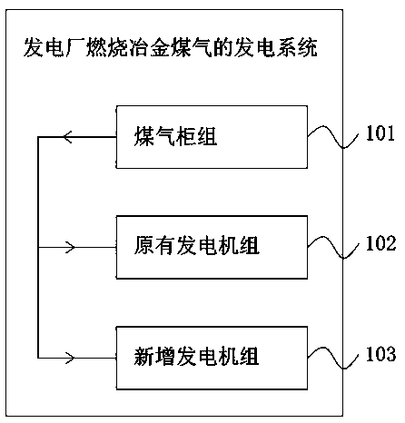
[0041] See figure 1 As shown, the power generation method of the power plant combustion metallurgical gas that the embodiment of the present invention provides:

[0042] S101, during the valley power period, the power plant does not generate electricity, and stores metallurgical gas in the gas container;

[0043] S102, during the peak power period, release the metallurgical gas from the gas container, and use the newly added generator set and the original generator set to generate electricity.

[0044] According to the embodiment of the present invention, during the off-peak power period, the power plant does not generate electricity, and stores the metallurgical gas in the gas container; during the peak power period, the metallurgical gas is released from the gas container, and the newly added generator set and the original The generator set generates electricity. In this way, during the off-peak power period, the gas container is fully utilized to store gas, and the power ...


PUM


Abstract

The invention provides a power generation method and system of power plant combustion metallurgy coal gas. The electricity cost of the iron and steel metallurgy enterprises can be lowered easily. Themethod includes the steps that during the valley electricity period, a power generating set of a power plant adopts the following operation mode for operation: power generation with output power lowered, power generation at some time periods, power generation without blending combustion of metallurgy coal gas, non-power generation or a combination of them, and the metallurgy coal gas is stored ina coal gas container; during a peak electricity or ordinary electricity period, the metallurgy coal gas is released out from the coal gas container, and the power generating set is used for generatingelectricity. The system comprises the coal gas container and the power generating set; the coal gas container is used for storing the metallurgy coal gas in the container during the valley electricity period, and releasing out the metallurgy coal gas from the coal gas container during the peak electricity or ordinary electricity period, and the power generating set is utilized for power generation; and the power generating set does not generate electricity during the valley electricity period or generates electricity at a rated output power without in all time periods, and during the peak electricity or ordinary electricity period, power generation is performed through the coal gas stored in the valley electricity period. The power generation method and system of the power plant combustion metallurgy coal gas are suitable for the technical field of coal gas power generation in the metallurgy enterprises.

Description

technical field [0001] The invention relates to the technical field of gas power generation in metallurgical enterprises, in particular to a power generation method and system for burning metallurgical gas in a power plant. Background technique [0002] During the production process of iron and steel metallurgical enterprises, a large amount of gas will be produced, which is an important secondary energy source for iron and steel enterprises. Its types mainly include blast furnace gas (Blast Furnace Gas, referred to as BFG), coke oven gas (CokeOven Gas, referred to as COG) and converter gas (Lindz-Donawitz Gas, referred to as LDG). Some of these gas are directly used in blast furnace hot blast stoves, coking furnaces, heating furnaces, equipment baking and various heat treatment furnaces in the enterprise. Power plants that sell gas to other companies to generate electricity. [0003] According to the statistics of China Iron and Steel Industry Association, the gas recycli...

Claims


Application Information

Patent Timeline
IPC IPC(8): F27D17/00
CPCF27D17/00
Inventor 不公告发明人
Owner 张俊哲
Learn More