Grenade bottom-row stern screwing device and using method

A stern and bottom row technology, applied in the direction of ammunition, weapon accessories, wrenches, etc., can solve the problems of inability to apply torque, affect product quality, and low efficiency, so as to ensure accuracy and reliability, avoid linear contact surface small, Effect of improving tightening efficiency

Pending Publication Date: 2019-04-23
HENAN NORTHERN HONGYANG ELECTROMECHANICAL CO LTD
View PDF0 Cites 0 Cited by
  • Summary
  • Abstract
  • Description
  • Claims
  • Application Information

AI Technical Summary

Problems solved by technology

At present, the commonly used devices mostly adopt the tightening method of chain pliers. The specific tightening process is as follows: the stern of the bottom row is manually pre-screwed into 2 to 3 buckles of the inner thread at the bottom of the body assembly, and the chain part of the chain pliers is wound around the bottom. Row the surface of the outer cone of the stern and lock it, then forcefully rotate the handle of the chain pliers clockwise to screw the bottom row of stern into the elastic body assembly in place. This traditional tightening method has the following disadvantages: 1) The bottom row The outer surface of the stern is a cone structure. Due to a certain taper between the chain and the bottom row stern, the chain and the cone surface form a cross-sectional line contact during the tightening process. The contact surface is small, and the slip between the chain and the bottom row stern is serious during the tightening process. Under the action of the rotating force, it is easy to form ring-shaped indentations and scratches (in the direction of the entire circumference) on the outer cone surface of the bottom row of sterns, which seriously affects product quality, and the efficiency is low, which is not conducive to mass production; 2) The bottom row of sterns needs to be tightened The torque cannot be applied, and the tightening force of the bottom row stern cannot be controlled in real time, resulting in poor accuracy and reliability of the bottom row stern tightening, which cannot meet the product design index requirements

Method used


Image

  • Grenade bottom-row stern screwing device and using method
  • Grenade bottom-row stern screwing device and using method
  • Grenade bottom-row stern screwing device and using method

Examples


Embodiment Construction

[0037] The following will be described in detail in conjunction with the technical solutions in the embodiments of the present invention:

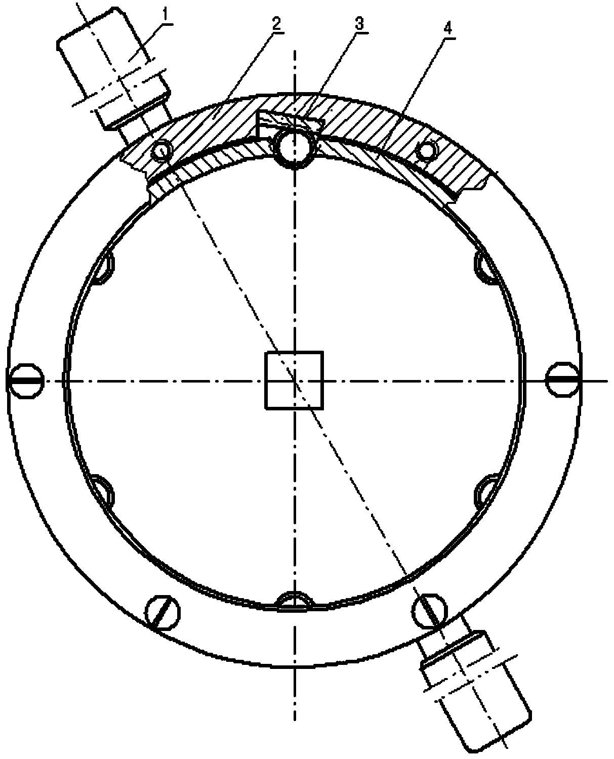
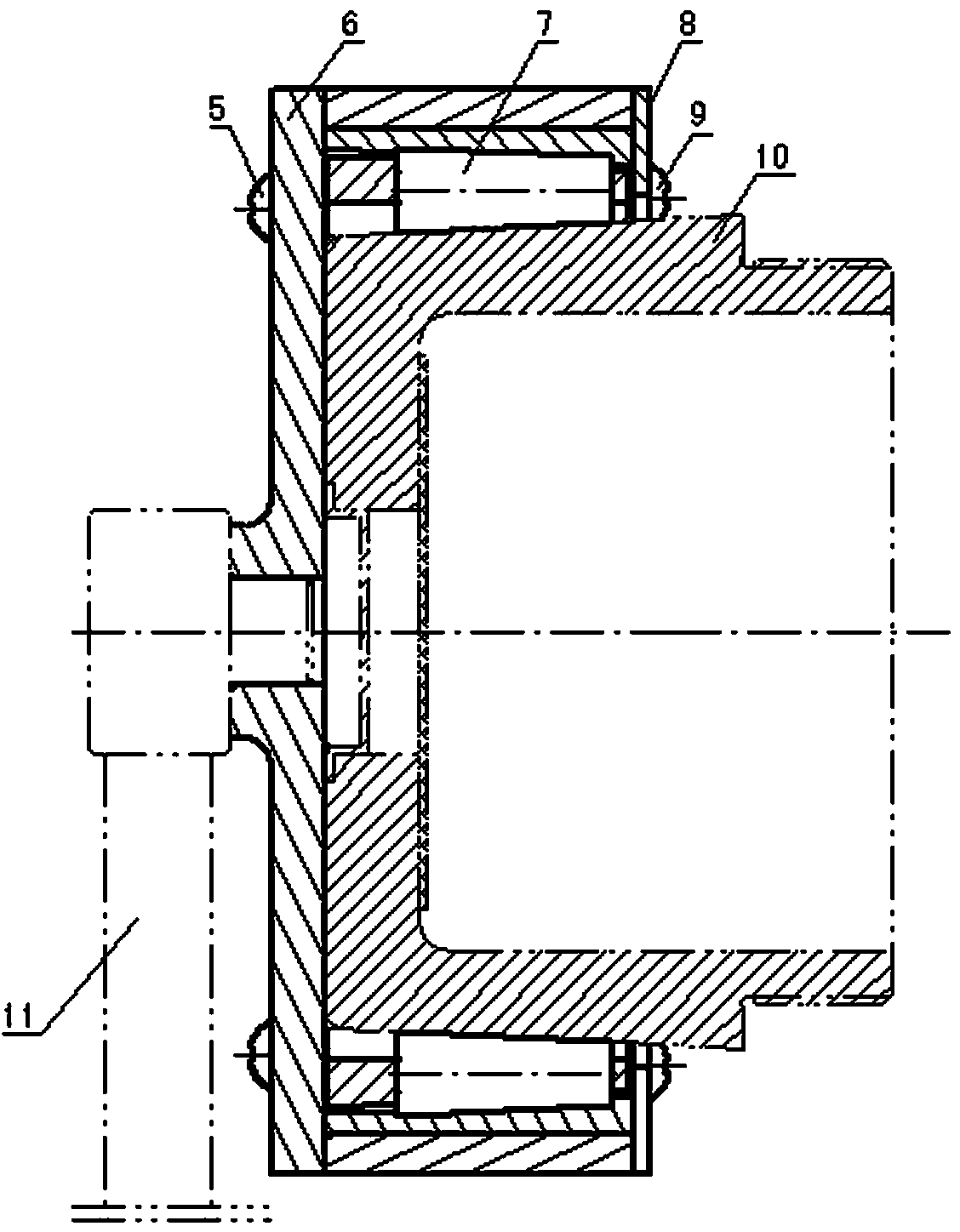
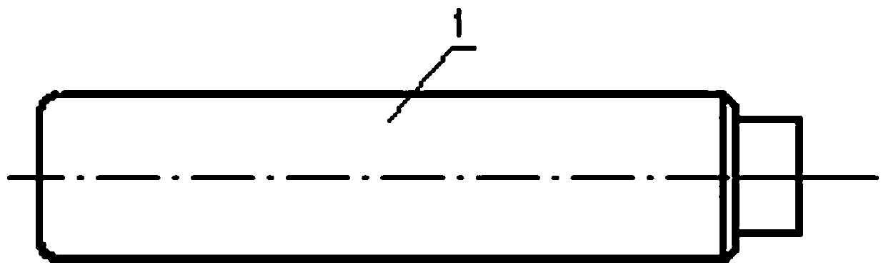
[0038] refer to Figure 1-15 As shown, the present invention proposes a grenade bottom row stern tightening device and its use method. The technical solution is: the conventional grenade bottom row stern tightening device of the present invention includes a frame body 2 and an inclined block 3 with combined assembly, and the retainer 4. Set in the middle of the frame body 2 to evenly distribute and fix the tapered rollers 7. The tapered surface of the tapered rollers 7 is attached to the inclined block 3 of the frame body. The upper end cover 6 and the lower end cover 8 pass through three M6× 16mm screws 5 and six M6×10mm screws 9 are respectively assembled on the upper end surface and the lower end surface of the frame body 2. When in use, the lower end cover 8 faces down and the wrench is inserted into the outer cone of the bottom row of...


PUM


Abstract

The invention discloses a grenade bottom-row stern screwing device and a using method. The grenade bottom-row stern screwing device comprises handles, a frame body, an oblique block, a retaining frame, M6*16 screws, an upper end cover, cone rolling columns, a lower end cover and M6*10 screws. When the device is used, the lower end cover faces downwards to enable a wrench to sleeve on the externalconical surface of a bottom-row stern, and the handles which are symmetrically welded to the external circular surface of the frame body is manually used, so that the cone rolling columns rotate alongthe axial line of the bottom-row stern in the frame body; meanwhile, the cone rolling columns move in the axial direction of the bottom-row stern under the action of the oblique block, the conical surface of each cone rolling column is clamped on the external conical surface of the bottom-row stern in a fastened manner, and the bottom-row stern is driven to be screwed together with a projectile assembly; and the force moment set on the mechanical torque wrench is exerted on the bottom-row stern, so that it is guaranteed that the screwing force of the bottom-row stern and the projectile assembly meets the requirement of a set value. According to the grenade bottom-row stern screwing device and the using method, screwing of the bottom-row stern and the projectile assembly under the action of the force moment can be achieved, the screwing efficiency of the bottom-row stern is improved, and the accuracy and reliability of screwing of the bottom-row stern are guaranteed.

Description

technical field [0001] The invention belongs to the technical field of mechanical assembly, and in particular relates to a grenade bottom row stern tightening device and a using method. Background technique [0002] The conventional grenade bottom row stern tightening technology is a new type of tightening technology. At present, the commonly used devices mostly adopt the tightening method of chain pliers. The specific tightening process is as follows: the stern of the bottom row is manually pre-screwed into 2 to 3 buckles of the inner thread at the bottom of the body assembly, and the chain part of the chain pliers is wound around the bottom. Row the surface of the outer cone of the stern and lock it, then forcefully rotate the handle of the chain pliers clockwise to screw the bottom row of stern into the elastic body assembly in place. This traditional tightening method has the following disadvantages: 1) The bottom row The outer surface of the stern is a cone structure. ...

Claims


Application Information

Patent Timeline
Patent Type & Authority Applications(China)
IPC IPC(8): F42B33/00B25B23/00
CPCF42B33/001B25B23/00
Inventor 张保良李哲王克艰
Owner HENAN NORTHERN HONGYANG ELECTROMECHANICAL CO LTD
Why Eureka
Try Eureka