
Hydraulic buffer assembly production system equipment and production process thereof

A technology of hydraulic buffer and production system, applied in assembly machines, metal processing equipment, metal processing, etc., can solve problems such as low tightening efficiency, inability to absorb nuts, and reduced feeding efficiency.

Inactive Publication Date: 2021-02-09
陈美香
View PDF1 Cites 1 Cited by
  • Summary
  • Abstract
  • Description
  • Claims
  • Application Information

AI Technical Summary

Problems solved by technology

[0004] However, the above piston assembly assembly equipment has the following problems: 1. The positioning accuracy of the connecting parts is poor, resulting in the need for repeated assembly when assembling other components, which reduces the production efficiency; 2. When the connecting parts and the shaft core are tightened, they cannot be fixed accurately The shaft core and the rotating mechanism cannot be quickly combined with the jig, resulting in low tightening efficiency; 3. Before the first stop ring is assembled, it needs to be checked for positive and negative. If the reverse side is facing up, it needs to be turned over, but the position of the first stop ring changes after turning , causing the first retaining ring to fail to return to its original position smoothly; 4. When feeding traditional nuts, other structures are needed to transition between the feeding mechanism and the tightening mechanism to complete the nut feeding, resulting in a complex structure; 5. Locking When the nuts are loaded, although all the nuts are placed horizontally, there is an angle between each nut when feeding, which makes it impossible to accurately absorb each nut and reduce the feeding efficiency

Method used


Image

  • Hydraulic buffer assembly production system equipment and production process thereof
  • Hydraulic buffer assembly production system equipment and production process thereof
  • Hydraulic buffer assembly production system equipment and production process thereof

Examples


Embodiment Construction

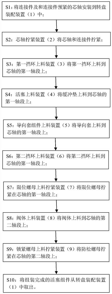
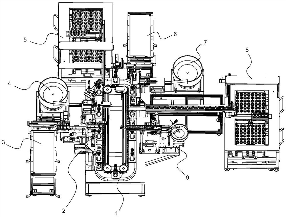
[0027] A hydraulic buffer assembly production system, the system includes piston assembly assembly production equipment, such as figure 2 The equipment shown includes a frame and a turntable assembly device 1 installed on the frame, a shaft core tightening device 2, a first retaining ring feeding device 3, a piston feeding device 4, a guide sleeve assembly feeding device 5, a second The retaining ring feeding device 6, the limit nut feeding and tightening device 7, the recovery valve feeding device 8 and the locking nut feeding and tightening device 9. The turntable assembly device 1 is sequentially provided with a connecting piece loading station, a shaft core tightening station, a first retaining ring feeding station, a piston feeding station, a guide sleeve assembly feeding station, and a second retaining ring feeding station. Station, limit nut feeding and tightening station, recovery valve feeding station and lock nut feeding and tightening station. The connector loadin...


PUM


Abstract

The invention relates to the field of hydraulic buffer assembly production. The invention provides a hydraulic buffer assembly production system. The system comprises piston component assembly production equipment. The equipment comprises a rack, and a turntable assembling device, a mandrel tightening device, a first baffle ring feeding device, a piston feeding device, a guide sleeve component feeding device, a second baffle ring feeding device, a limiting nut feeding tightening device, a rebuilt valve feeding device and a locking nut feeding tightening device which are mounted on the rack, ajig mechanism used for vertically fixing a connecting piece is installed on an assembling frame mechanism in a sliding manner, and the jig mechanism continuously and annularly circulates on the assembling frame mechanism. The mandrel tightening device, the first baffle ring feeding device, the piston feeding device, the guide sleeve component feeding device, the second baffle ring feeding device,the limiting nut feeding tightening device, the rebuilt valve feeding device and the locking nut feeding tightening device are sequentially arranged at the periphery of the turntable assembling device, so that the devices act at the same time, and the assembling efficiency is improved.

Description

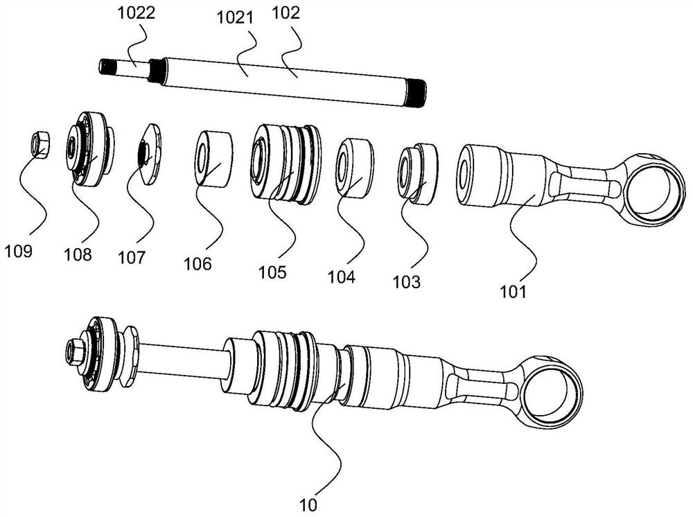
technical field [0001] The invention relates to the field of hydraulic buffer assembly production, in particular to a hydraulic buffer assembly production system and a production process thereof. Background technique [0002] The shock absorber relies on hydraulic damping to buffer and decelerate the objects acting on it to a stop, which plays a certain degree of protection. It is suitable for mechanical equipment such as lifting transportation, elevators, metallurgy, port machinery, railway vehicles, etc. It is used as a safety buffer device to prevent mechanical damage caused by hard collisions during work. The piston assembly is an important part of the hydraulic shock absorber movement execution part. The piston assembly includes a connecting piece, a shaft core, a first retaining ring, a piston, a guide sleeve assembly, a second retaining ring, a limit nut, a recovery valve and a lock nut ; The right end of the shaft core is threadedly connected with the connector, the...

Claims


Application Information

Patent Timeline
IPC IPC(8): B23P21/00
CPCB23P19/001B23P21/004
Inventor 陈美香陈号
Owner 陈美香
Learn More