Power transmission line vibration monitoring device
A technology for vibration monitoring and power transmission lines, applied in measuring devices, measuring ultrasonic/sonic/infrasonic waves, instruments, etc., can solve difficulties, power sensors are vulnerable to electromagnetic interference, on-site power supply, monitor the entire file of wire distributed monitoring and other problems, to achieve Strong function, avoid electromagnetic interference, high reliability effect
- Summary
- Abstract
- Description
- Claims
- Application Information
AI Technical Summary
Problems solved by technology
Method used
Image
Examples
Embodiment 1
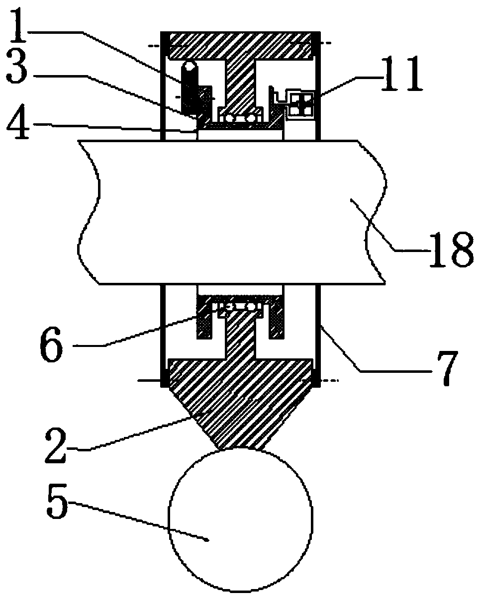
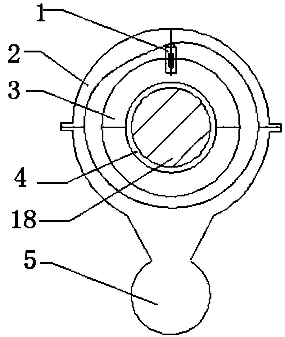
[0056] A transmission line vibration monitoring device provided by an embodiment of the present invention, its front view is as follows figure 1 As shown, the left view is as figure 2 As shown, it mainly includes: outer sleeve 2, inner sleeve 3, weight 5, end cap 7 and fiber grating sensing unit 1;
[0057] Wherein, the outer sleeve 2 is slidingly connected with the inner sleeve 3; the inner sleeve 3 is sleeved on the wire to be tested;
[0058] The weight 5 is connected below the outer sleeve 2;
[0059] The fiber grating sensing unit 1 is fixedly installed on the outer wall of the inner sleeve 3 .
[0060] The inner sleeve 3 is used to clamp the wire, and is formed by connecting two parts symmetrically with upper and lower bolts;
[0061] The inner sleeve 3 is in soft contact with the wire 18 through a rubber collar 4, and is fixed by bolts to ensure that it will not rotate and slip relative to the wire 18;
[0062] The outer sleeve 2 can rotate around the axis of the w...
Embodiment 2
[0070] The monitoring method for the torsional vibration of the transmission line is as follows:
[0071] The lower end of the outer sleeve 2 is connected to a spherical weight 5. When the wire 18 and the inner sleeve 3 are twisted relative to the ground, the gravity of the weight 5 can ensure that the outer sleeve 2 remains stationary relative to the ground, thus causing the inner and outer sleeves to When the relative rotation of the inner and outer sleeves occurs, the gap between the inner sleeve 3 and the inner wall of the front end of the outer sleeve 2 will change. At this time, the fiber grating sensing unit 1 fixed on the inner sleeve will be affected. The pressure and strain will change, and this change will lead to the change of the central wavelength of the grating reflected wave. The corresponding relationship between the strain of the fiber grating sensing unit 1 and the change of the reflection center wavelength of the fiber grating can determine the rotation ang...
Embodiment 3
[0073] The monitoring methods for horizontal and vertical vibration of conductors are as follows:
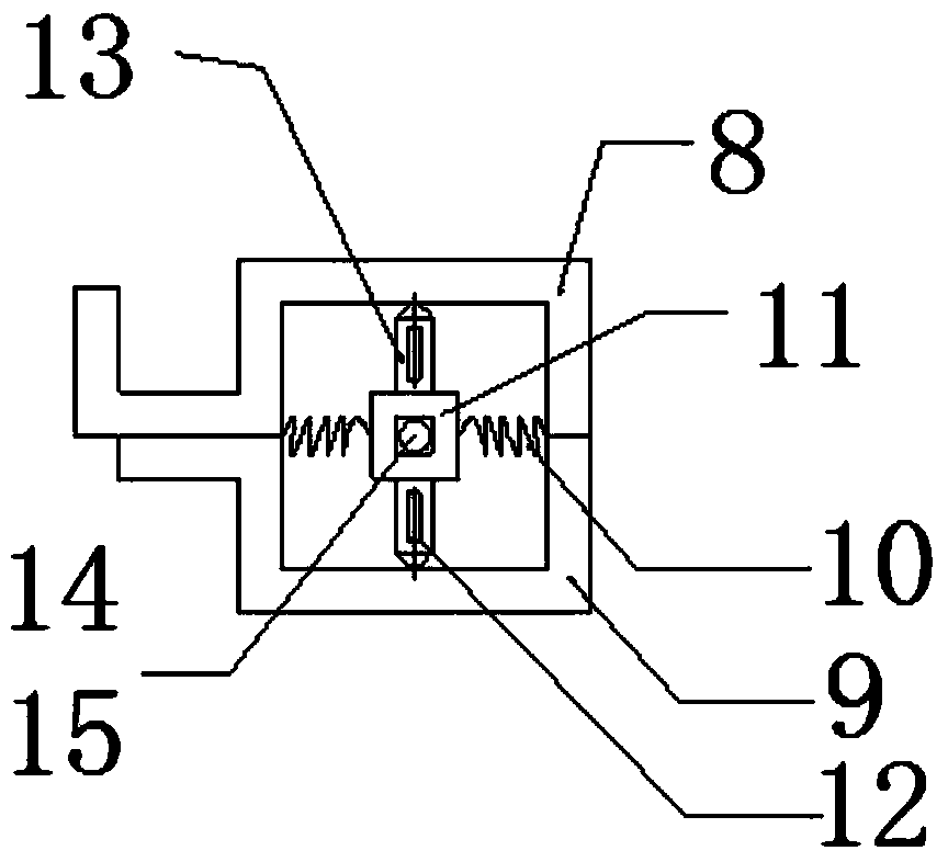
[0074] When the wire 18 vibrates in the horizontal and vertical directions, the mass block 11 will exert pressure on the fiber grating sensors 12, 13, 14, 15 due to inertia, causing the strain of the fiber grating sensors 12, 13, 14, 15 to change, This change will lead to the change of the central wavelength of the grating reflected wave, which is transmitted back to the fiber grating demodulator 24 through the optical fiber, and then according to the horizontal and vertical accelerations calibrated in advance before the installation of the whole device and the fiber grating sensors 12, 13, 14, 15 strain and the corresponding relationship between the reflection center wavelength of the fiber grating, the acceleration of the wire 18 in the horizontal and vertical directions can be determined, thereby realizing the monitoring of the horizontal and vertical vibration of the wire.
PUM
 Abstract
Description
Claims
Application Information
 - R&D
- Intellectual Property
- Life Sciences
- Materials
- Tech Scout
- Unparalleled Data Quality
- Higher Quality Content
- 60% Fewer Hallucinations
Browse by: Latest US Patents, China's latest patents, Technical Efficacy Thesaurus, Application Domain, Technology Topic, Popular Technical Reports.
© 2025 PatSnap. All rights reserved.Legal|Privacy policy|Modern Slavery Act Transparency Statement|Sitemap|About US| Contact US: help@patsnap.com


