Organic electroluminescent device

An electroluminescent device and electroluminescent technology, which can be applied in the direction of electro-solid devices, electrical components, semiconductor devices, etc., and can solve problems such as unfavorable OLED display applications and excessively wide spectrum.

Inactive Publication Date: 2019-04-23
BEIJING ETERNAL MATERIAL TECH +1
View PDF6 Cites 3 Cited by
  • Summary
  • Abstract
  • Description
  • Claims
  • Application Information

AI Technical Summary

Problems solved by technology

However, due to the intramolecular CT state transition of TADF materials, there is a problem that the spectrum is too broad, which is not conducive to the application of OLED displays.

Method used


Image

  • Organic electroluminescent device
  • Organic electroluminescent device
  • Organic electroluminescent device

Examples


Embodiment 1

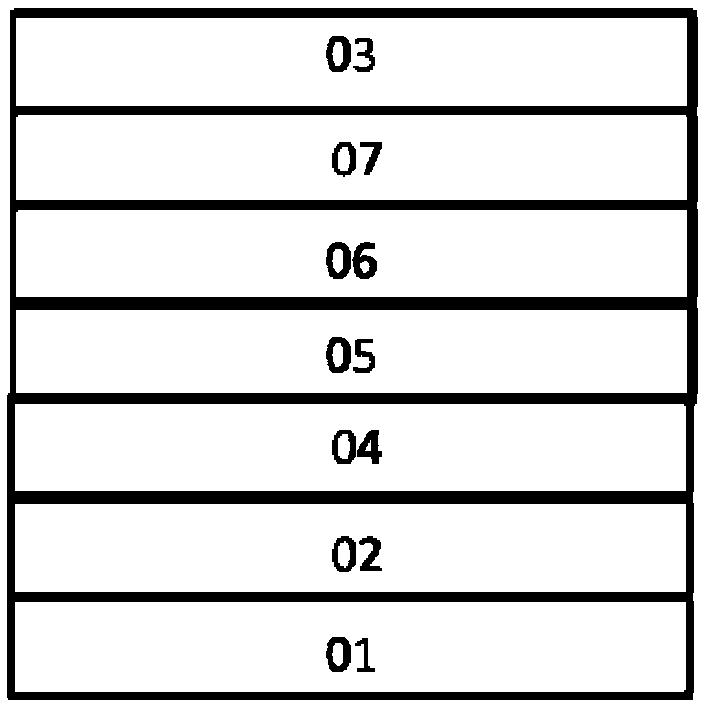
[0097] In this embodiment, blue light-emitting devices are prepared, and these devices have the following properties: image 3 structure shown. The light-emitting layer contains a host material (Host 1) and a fluorescent doped dye (BD 1), wherein the Host 1 material is a material with TADF properties, and the first triplet state of its (n-π) excited state is slightly smaller than that of CT The first triplet state (0.1eV) of the excited state, the singlet energy level of BD1 is 2.75eV, which is lower than the singlet energy level of Host 1. The comparative example uses mCBP and BD2. The main material mCBP does not have CT state transitions, and cannot realize the reverse gap crossing process (RISC) between the excited state triplet state energy level and the excited state singlet state energy level; BD2 has no Hindering group protection. The material structure used in the device is as follows:

[0098]

[0099] The device structure of this embodiment is as follows:

[0...

Embodiment 2

[0119] In this embodiment, green light-emitting devices are prepared, and the structures of these devices are shown in the attached image 3 shown. The light-emitting layer contains double-host TCTA and CzTrz and a fluorescent dopant dye (GD 1). Among them, TACTA and CzTrz can form exciplexes (ACS Appl. Mater. Interfaces 2016, 8, 3825-3832) to achieve delayed fluorescence. GD1 is a fluorescent dye protected by a bulky hindering group. In the comparative example, TCTA and CzTrz are respectively used as main materials, and GD2 is a contrasting fluorescent dye. The material structure used in the device is as follows:

[0120]

[0121] An organic electroluminescence device was prepared in the same manner as in Example 1 above, and the structure of the light-emitting device was as follows:

[0122] ITO(150nm) / NPB(40nm) / TCTA:(100%)CzTrz:(5%)GD 1(30nm) / Bphen(20nm) / LiF(0.5nm) / Al(150nm)

[0123] Among them, the percentages in parentheses before CzTrz and GD1 indicate the doping...

Embodiment 3

[0139] In this example, red light-emitting devices doped with fluorescent dyes are prepared, and these devices have the attached image 3 structure shown. The light-emitting layer includes a host material (Host3) and red fluorescent doped dye (RD 1). Wherein Host3 is a host material with delayed fluorescence properties. RD1 is a fluorescent dye protected by a bulky hindering group. In the comparative example, Host4 without TADF properties was selected as the main body, and RD2 was used as the contrast dye. The material structure used in the device is as follows:

[0140]

[0141] Prepare an organic electroluminescence device in the same manner as in Example 1 above, and the structure of the light-emitting device is as follows:

[0142] ITO(150nm) / NPB(40nm) / Host 3:(5%)RD 1(30nm) / Bphen(20nm) / LiF(0.5nm) / Al(150nm)

[0143] Among them, the percentage in parentheses before RD1 indicates the fluorescent dye doping concentration.


PUM


Abstract

The invention discloses an organic electroluminescent device. The organic electroluminescent device comprises an anode, a cathode and an organic functional layer. The organic functional layer at leastcomprises a light-emitting layer, the main body material of the light-emitting layer is a thermally activated delayed fluorescent material, the energy difference [delta]Est of the excited singlet state of the main body material and the lowest excited triplet state of 77K meets a formula (1), and the energy level relation of the main body material and the guest material meets a formula (2): in theformula (1),[delta]Est(main body)<0.3eV, and in the formula (2), ES1(main body)>ES1(guest material), the guest material is selected from a type of fluorochrome with a special structure, the nuclear parent group of the compound is a triplet state energy level T1 larger than a large sterically hindered group of 2.2eV without excited state energy distribution. The device fully utilizes the triplet state energy of the main body material during electroluminescence so as to effectively improve the luminous efficiency of the device.

Description

technical field [0001] The present invention relates to the technical field of organic electroluminescence, and more particularly relates to a novel organic electroluminescence device. Background technique [0002] Under electro-excited conditions, organic electroluminescent devices will generate 25% singlet and 75% triplet excitons. Traditional fluorescent materials can only utilize 25% of the singlet excitons due to spin-forbidden reasons, so the external quantum efficiency is only limited within 5%. Almost all triplet excitons can only be lost as heat. To improve the efficiency of organic electroluminescent devices, triplet excitons must be fully utilized. [0003] In order to utilize triplet excitons, researchers have proposed many methods. Most notable is the utilization of phosphorescent materials. Due to the introduction of heavy atoms, the phosphorescent material has a spin-orbit coupling effect, so it can make full use of 75% of the triplet state, thereby achiev...

Claims


Application Information

Patent Timeline
Patent Type & Authority Applications(China)
IPC IPC(8): H01L51/50
CPCH10K50/11H10K2101/40
Inventor 高文正任雪艳
Owner BEIJING ETERNAL MATERIAL TECH
Why Eureka
Try Eureka